
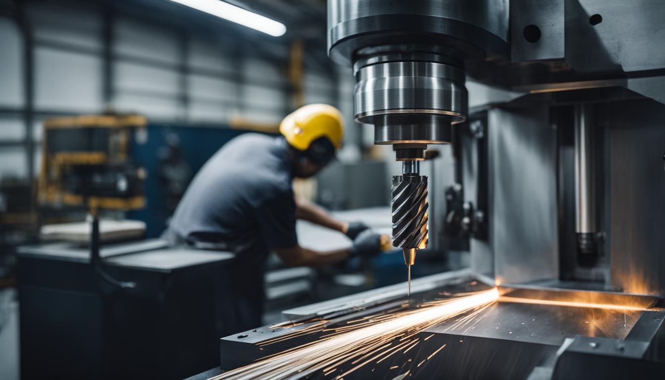
Advancing beyond basic G-code requires a deeper understanding of CNC machine capabilities and programming techniques. Mastering intermediate skills significantly enhances efficiency, reduces manual intervention, and unlocks the potential for complex part manufacturing. These advanced methods are crucial for optimizing production in modern machine shops.
This guide explores five essential advanced CNC programming skills: custom macro G-code, 4th-axis rotary moves, subprogram subroutine calls, dynamic adaptive toolpaths, and thread milling programming. Each skill offers distinct advantages for tackling more intricate machining challenges.
Writing Custom Macro G-Code
Custom macro G-code programming introduces variables, mathematical operations, and logical statements into CNC programs, transforming static code into dynamic, adaptive routines. This capability is often referred to as Fanuc Custom Macro B on Fanuc-type controls, though similar functionalities exist across various control systems like Haas.
Variables, identified by a pound or hash symbol (#) followed by a number, act as storage locations for data such as coordinates, counter values, or offset adjustments. Local variables (#1-#33) are temporary and cleared after a macro call, ideal for passing arguments. Common variables (#100-#199) persist until power-off, while higher-numbered common variables (#500-#999) can be non-volatile, retaining values even after the machine is shut down.
Macros enable parametric programming, allowing a single program to machine a family of parts with varying dimensions by simply changing variable values. This reduces manual programming time, minimizes human error, and ensures consistency. Custom macros are also used for offset control, creating custom cycles, and simulating non-standard tool motions.
Calling a macro typically involves the G65 preparatory command, which executes a one-shot macro with local variables. Some controls also support G66 for modal macro calling, where the macro executes continuously until canceled by G67. Custom G-codes can even be aliased to specific macro program numbers in the control’s parameters, simplifying calls.
Programming 4th-Axis Rotary Moves
| Feature | Thread Milling | Tapping |
|---|---|---|
| Speed | Slower, especially for large threads | Faster for high-volume production |
| Tool Flexibility | One tool can cut many thread sizes | One tap per size/thread |
| Thread Fit Control | High control, adjustable | Limited, fixed by tap size |
| Tool Breakage Risk | Lower, especially in blind holes | Higher, particularly in hard materials |
| Internal/External Threads | Both internal and external | Primarily internal |
Integrating a 4th-axis rotary table expands a CNC mill’s capabilities from 3-axis planar machining to complex rotational and helical operations. This additional axis, typically designated as ‘A’ (rotation around X), ‘B’ (rotation around Y), or ‘C’ (rotation around Z), allows for indexing, where the part is rotated to a specific angle and then machined, or simultaneous contouring, where the rotary axis moves concurrently with linear axes.
Programming 4th-axis moves involves specifying the rotary axis position in degrees. For indexing, the machine rotates to a new angle (e.g., A90.0) and then performs standard 3-axis operations. Simultaneous 4-axis machining requires coordinated motion between the rotary and linear axes, often generated by CAM software, to create complex curved surfaces or helical features. This capability is particularly valuable for aerospace and medical device manufacturing.
When programming rotary moves, careful consideration of work offsets and tool length compensation is essential. The center of rotation for the 4th axis must be accurately defined, and toolpaths must account for the changing orientation of the workpiece relative to the cutting tool. Modern CAM systems simplify this by generating the complex G-code required for multi-axis interpolation.
Subprogram Subroutine Calls
Subprograms, also known as subroutines, are self-contained blocks of G-code that perform specific, repetitive tasks. They are called from a main program, execute their instructions, and then return control to the main program. This modular approach significantly reduces program length, simplifies debugging, and enhances code reusability.
A subprogram is typically stored under its own program number (e.g., O6001). The M98 command calls a subprogram, often with an ‘L’ address to specify the number of repetitions (e.g., M98 P6001 L5). The subprogram concludes with an M99 command, which returns execution to the line immediately following the M98 call in the main program.
Subprograms can be nested, meaning one subprogram can call another, up to several levels deep, depending on the control system. This hierarchical structure is beneficial for complex operations with repeated patterns at different locations or orientations. Local subprograms can also be defined within the main program, often using N sequence numbers and M97, eliminating the need for a separate O-number file.
Dynamic Adaptive Toolpaths
Dynamic adaptive toolpaths represent a significant advancement in roughing strategies, optimizing material removal rates and extending tool life. Unlike traditional offset toolpaths that can lead to inconsistent tool engagement and sudden load spikes, adaptive strategies maintain a nearly constant tool engagement angle throughout the cut.
These toolpaths generate smooth, spiraling, or trochoidal motions that roll into corners, preventing the tool from engaging at full width. This consistent chip load reduces stress on the cutting tool and spindle, allowing for deeper axial cuts and higher feed rates. The result is faster machining times, improved surface finish, and significantly longer tool life.
Adaptive machining is particularly effective for deep pockets, hard materials, and complex geometries. It minimizes heat buildup and distributes cutting forces evenly along the entire flute length, rather than concentrating them at the tool tip. Modern CAM software is essential for generating these complex toolpaths, often incorporating simulation and optimization features.
Thread Milling Programming
Thread milling is a versatile method for creating internal and external threads using a rotating cutting tool with a helical interpolation motion. This technique offers several advantages over traditional tapping, including greater control over thread fit, the ability to machine a wide range of thread sizes with a single tool, and reduced risk of tool breakage, especially in hard materials or blind holes.
Programming thread milling involves a helical interpolation path, typically using G02 (clockwise) or G03 (counter-clockwise) commands with simultaneous linear (X, Y) and axial (Z) movements, combined with an ‘I’ or ‘J’ address for the arc center and a ‘K’ address for the pitch. Cutter compensation (G41/G42) is often employed to control the final thread diameter and achieve desired tolerances.
Thread milling inserts are commonly made from carbide, offering high hardness and wear resistance for various materials like steels, stainless steels, and non-ferrous metals. Single-point, multi-form, and indexable thread mills are available, each suited for different applications and production volumes.
Standard thread tolerances, such as ISO 6H for internal threads and 6g for external threads, are crucial for ensuring proper fit and function. These tolerances define the acceptable dimensional limits and are influenced by factors like thread coarseness and engagement length.