
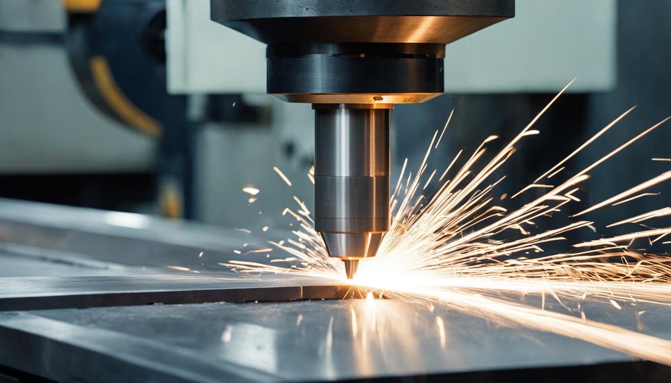
Milling machine operation is a foundational subtractive manufacturing process, meticulously shaping raw material into desired geometries using rotating multi-point cutting tools. This method is indispensable across industries, from aerospace to medical device production, due to its capacity for high precision and repeatability. Modern Computer Numerical Control (CNC) milling systems automate complex tool paths, significantly enhancing efficiency and accuracy.
Rotary Cutter Material Removal Principles
Material removal in milling occurs as a rotary cutter, typically a multi-point tool, engages a workpiece at high speed. Each cutting edge takes a ‘bite,’ shearing off material in the form of chips. This controlled process transforms a simple block into intricate components, with the operator determining workpiece positioning and the tool executing the precise cuts.
Cutting tools are manufactured from various materials, each selected for specific applications based on durability, strength, and wear resistance. High-speed steel (HSS) offers toughness and affordability for general use, while cemented carbide is the industry standard for high-performance machining due to its superior heat resistance and rigidity.
Advanced tool materials like ceramics, cubic boron nitride (CBN), and polycrystalline diamond (PCD) are employed for cutting hard, abrasive, or non-ferrous materials at very high speeds. Coatings such as Titanium Nitride (TiN) or Aluminum Titanium Nitride (AlTiN) further enhance tool life and performance by reducing friction and increasing heat resistance.
Surface Facing and End Pocketing Techniques
| Tolerance Category | Typical Range (Inches) | Typical Range (Millimeters) | Application |
|---|---|---|---|
| Standard | ±0.005″ | ±0.127 mm | General purpose, prototypes |
| Tight | ±0.002″ | ±0.050 mm | Critical fits, mating surfaces |
| Precision | ±0.001″ to ±0.0005″ | ±0.025 mm to ±0.0127 mm | Aerospace, medical, reamed holes |
Face milling is a primary operation designed to create flat, smooth surfaces on a workpiece. The cutting tool, often a shell mill or specialized face mill, rotates perpendicular to the workpiece surface, engaging with multiple inserts to remove material efficiently. This process is crucial for establishing a stable datum for subsequent machining operations.
Achieving an optimal surface finish in face milling requires careful consideration of tool selection and cutting parameters. Using wiper-style inserts, reducing feed and depth of cut, and maintaining tight control over axial and radial runout are key strategies. These practices minimize scallop marks and ensure surface integrity, often eliminating the need for further grinding.
End pocketing involves creating recessed cavities within a part’s outer contour. These pockets can be simple geometric shapes or complex multi-depth features, typically machined using end mills. The process often begins with roughing passes to remove bulk material, followed by finishing passes for dimensional accuracy and surface quality.
Common challenges in pocket milling include tool deflection, chatter, and poor chip evacuation. Long tools used for deep pockets are prone to bending, leading to chatter marks and dimensional inaccuracies. Proper chip evacuation, often aided by air blasts or coolant, prevents re-cutting and tool damage.
Feed Rate and Speed Execution Dynamics
Calculating the correct spindle speed (RPM) and feed rate (IPM) is critical for efficient milling, directly impacting tool life, surface finish, and material removal rates. Spindle speed is determined by the desired surface feet per minute (SFM) and tool diameter, while feed rate considers RPM, chip load (feed per tooth), and the number of cutting edges.
Chip load, defined as the thickness of material removed by each cutting edge per revolution, is a fundamental parameter. An optimal chip load ensures efficient chip formation, carries heat away from the cutting edge, and reduces cutting forces. Too high a chip load can cause tool breakage, while too low can lead to rubbing and work hardening.
Standard machining tolerances in CNC milling vary based on the process and required precision. General applications typically target ±0.005 inches (±0.127 mm), while tight tolerances for critical fits can reach ±0.002 inches (±0.050 mm). Precision applications, such as reamed holes, may demand tolerances as fine as ±0.0005 inches (±0.0127 mm).
Depth of cut (DOC) and radial engagement are also crucial parameters. A common guideline for roughing operations limits radial DOC to 50% of the cutter diameter to manage cutting forces and tool deflection. Axial DOC for aluminum can be up to 1.5 times the tool diameter, but proper chip evacuation and coolant delivery are essential.
Coolant Flow and Thermal Management
Coolants are instrumental in machining, serving multiple critical functions beyond just heat reduction. They provide lubrication to minimize friction between the tool and workpiece, flush away chips from the cutting zone, and protect both the machine and part from corrosion. The specific type and concentration of coolant are tailored to the workpiece material and machining operation.
Various coolant types are available, including soluble oils, synthetic fluids, semi-synthetic fluids, and neat oils. Soluble oils, mixed with water, are versatile for general machining. Synthetic coolants, water-based with chemical lubricants, offer superior cooling for high-speed operations and hard materials.
Coolant delivery methods range from flood coolant, which submerges the cutting zone, to Minimum Quantity Lubrication (MQL), which applies a fine mist of lubricant. Air cooling is also used for sensitive materials like certain plastics, where thermal shock from liquid coolants could cause warping. Proper coolant management, including tramp oil removal, extends fluid and tool life.
Coordinated Axis Movement and Interpolation
CNC milling machines rely on precise coordination of multiple axes to execute complex tool paths. A typical 3-axis machine moves along X (left-right), Y (front-back), and Z (up-down) linear axes. More advanced machines, such as 5-axis systems, add rotational axes to achieve even more intricate geometries.
Interpolation is the mathematical process within the CNC controller that generates intermediate points along a programmed tool path, ensuring smooth and accurate motion between specified coordinates. Without interpolation, tool movement would be stepwise and mechanically unstable, leading to poor surface finish and dimensional inaccuracies.
Linear interpolation enables straight-line movements by coordinating the simultaneous motion of two or more axes. Circular interpolation allows the tool to follow arc-shaped paths, crucial for machining curved surfaces. Multi-axis interpolation extends this coordination to complex three-dimensional movements, managing tool angles and maintaining synchronized motion for high-precision components like aerospace impellers.