
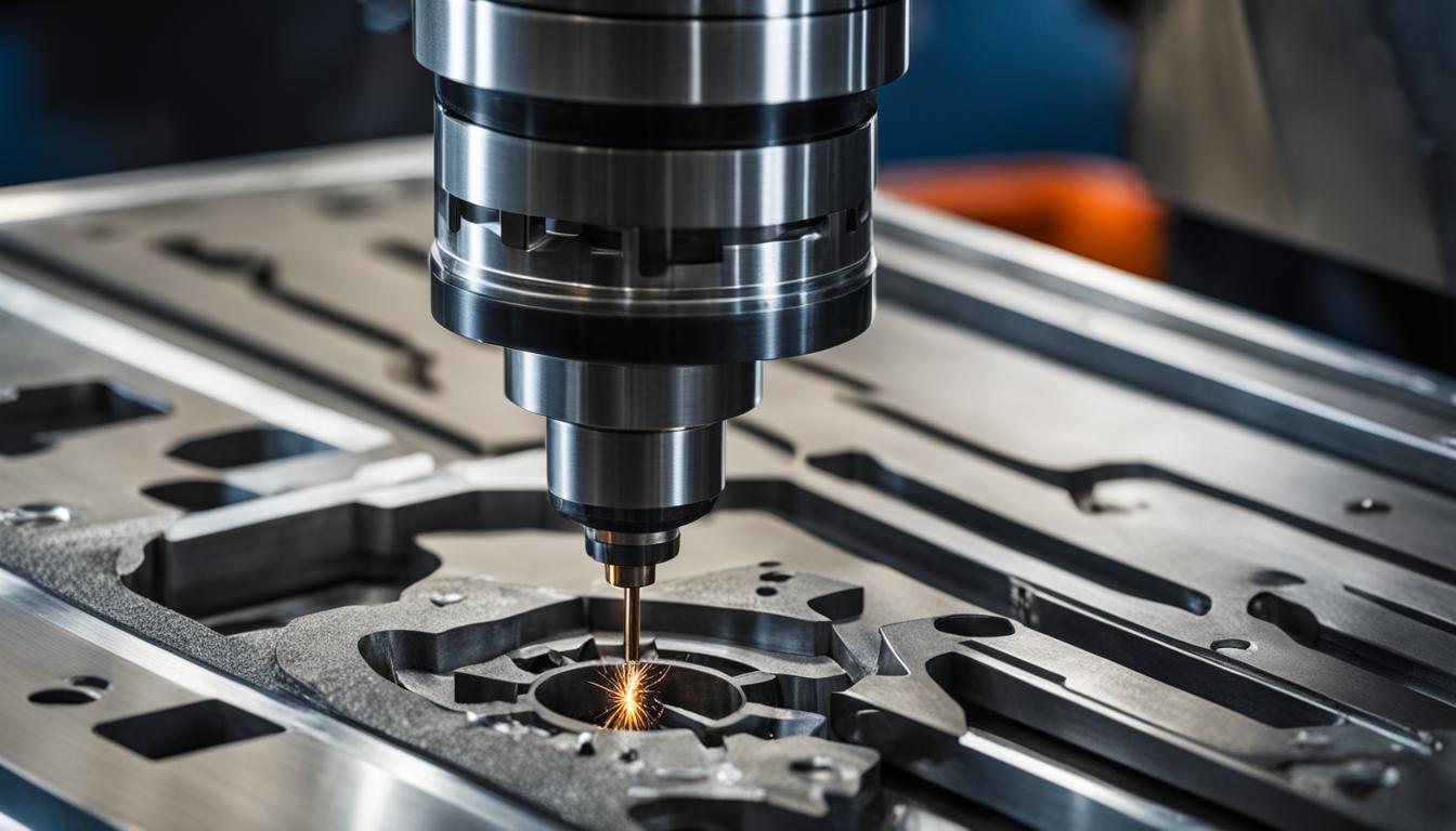
Intermediate CNC machinists elevate their craft by mastering fundamental precision skills. Accurate part production relies on a deep understanding of machine setup, programming adjustments, and rigorous inspection methods. These core competencies differentiate skilled operators from basic machine tenders.
Precision machining demands meticulous attention to detail at every stage of the manufacturing process. From initial setup to final inspection, each step contributes significantly to the overall quality and dimensional accuracy of the finished component.
Precise Work Coordinate System Setup
Establishing accurate work coordinate systems (WCS) is foundational for precision CNC machining. The machine’s controller uses these offsets (e.g., G54, G55, G56) to define the workpiece’s position relative to the machine’s home position. Errors in this setup directly translate to dimensional inaccuracies in the final part.
Modern CNC shops increasingly utilize probing systems to automate and enhance WCS accuracy. These systems, integrated directly into the machine, measure workpiece position, tool length, and feature dimensions, feeding data back to the controller for automatic offset updates. This significantly reduces manual setup time and improves repeatability compared to traditional methods like edge finders or indicators.
Workholding methods also play a critical role in maintaining WCS integrity. Secure clamping prevents movement, vibration, or distortion during cutting, ensuring the part remains precisely located throughout the machining process. Common methods include machine vises, chucks, collets, and custom fixtures, each selected based on part geometry, material, and required precision.
Interpreting Complex GD&T Drawings
| Ra Value (µm) | Ra Value (µin) | Description | Typical Application |
|---|---|---|---|
| 3.2 | 125 | Standard ‘as-machined’ finish with visible tool marks. | General mechanical elements, brackets, internal parts. |
| 1.6 | 63 | Moderate smoothness, reduced tool marks. | Precision parts, moderate sealing surfaces. |
| 0.8 | 32 | Smooth to the touch, minimal tool marks. | Sliding components, enhanced aesthetics. |
| 0.4 | 16 | Very smooth, almost polished appearance. | Critical sealing surfaces, medical parts. |
Geometric Dimensioning and Tolerancing (GD&T) provides a universal language for communicating design intent on engineering drawings. Intermediate machinists must possess a strong ability to interpret these symbols and their associated feature control frames to produce parts that meet functional requirements.
The ASME Y14.5 standard is the authoritative guideline for GD&T, establishing symbols, definitions, and rules for geometric dimensioning and tolerancing. This standard ensures clear communication throughout the design and manufacturing process, reducing guesswork and improving quality.
Understanding various GD&T symbols, such as flatness, perpendicularity, position, and profile of a surface, is essential. Each symbol controls specific geometric characteristics, often referencing datums—theoretically exact points, lines, or planes derived from real features on the part. The feature control frame specifies the geometric characteristic, tolerance value, material condition modifiers, and datum references.
Beyond ASME Y14.5, the ISO 2768 standard provides general tolerances for linear, angular, and geometric dimensions when specific tolerances are not explicitly stated on a drawing. This standard categorizes tolerances into classes like ‘fine’ (f), ‘medium’ (m), ‘coarse’ (c), and ‘very coarse’ (v), with ‘medium’ being a common general-purpose default for CNC machining.
Adjusting Cutter Radius Offsets Effectively
Cutter radius compensation (CRC), typically managed with G41 (left compensation) and G42 (right compensation) G-codes, is crucial for maintaining dimensional accuracy, especially on contours. Without it, the programmed toolpath, which usually follows the tool’s centerline, would result in an undersized part by the tool’s radius.
Implementing CRC requires defining the cutter’s radius in the machine’s offset table (D-code) and calling the appropriate G-code (G41 or G42) before the cutting move. The direction of compensation (left or right) is determined by imagining walking along the programmed path in the direction of cut.
Proper lead-in and lead-out moves are vital for smooth engagement and disengagement of cutter compensation. Compensation activates after a linear or arc movement and must be canceled with G40 after the path is completed to avoid unexpected tool movements. This technique is particularly useful for compensating for tool wear or running the same part with different tool diameters without reprogramming the entire toolpath.
Accurate Part Inspection with Micrometers
Precision machining necessitates precise measurement. Micrometers are fundamental tools for intermediate machinists, offering accuracy typically to 0.01mm or 0.0001 inches, surpassing vernier calipers. Mastering their use and calibration is non-negotiable for quality control.
Before any measurement, the micrometer must be clean and properly calibrated. For a 0-1 inch or 0-25mm micrometer, this involves gently closing the spindle against the anvil and checking that the barrel line aligns with the zero mark on the thimble. Adjustments are made if misalignment occurs.
For larger micrometers or to verify accuracy across the entire range, certified gauge blocks or setting rods are used. These standards have known, precise thicknesses, allowing machinists to confirm the micrometer’s readings at multiple points. Consistent application of measuring force, typically achieved with a ratchet stop, is crucial for repeatable and accurate readings.
Fine-Tuning Speeds and Feeds for Optimal Results
Optimizing speeds and feeds is a critical skill that directly impacts tool life, surface finish, and machining efficiency. These parameters—spindle speed (RPM) and feed rate (IPM or mm/min)—must be carefully balanced according to material properties, tool geometry, and machine rigidity.
Chip load, defined as the thickness of material removed by a single cutting edge per revolution, is a key metric. An optimal chip load ensures clean shearing, reduces heat generation, and prevents premature tool wear or built-up edge. Too low a chip load can cause rubbing and excessive heat, while too high can lead to tool breakage.
Calculating chip load involves the feed rate, spindle speed, and the number of cutting edges (flutes) on the tool. Tool manufacturers often provide recommended starting parameters, which machinists then fine-tune based on observation of chip formation, cutting sound, and surface finish.
Material characteristics significantly influence optimal speeds and feeds. Softer materials like aluminum generally require higher cutting speeds and can tolerate higher feed rates than harder materials such as steel or titanium. For instance, aluminum might be machined at 8,000–12,000 RPM, while steel requires 200–400 RPM. Surface finish requirements also dictate adjustments; finer finishes often necessitate higher spindle speeds and lower feed rates.
The standard ‘as-machined’ surface roughness for CNC parts is typically Ra 3.2 µm (125 µin), suitable for general mechanical components. Achieving finer finishes, such as Ra 1.6 µm or 0.8 µm, requires additional finishing passes and tighter control over cutting parameters, which increases cost.