
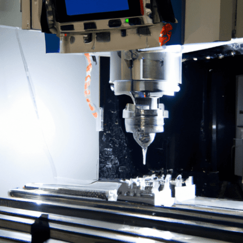
Effective CNC milling relies on precise control over cutting parameters, directly influencing material removal rates and tool life. Achieving optimal performance requires a deep understanding of how axial depth of cut (ADOC) and radial depth of cut (RDOC), often referred to as stepover, interact with material properties and tool geometry. Modern engineering practices leverage advanced strategies to maximize efficiency and surface quality.
Standard CNC machining tolerances typically range from ±0.05 mm to ±0.13 mm for most milling and turning operations on metal parts, with plastics often requiring wider tolerances around ±0.25 mm due to thermal sensitivity and flexibility. Tighter tolerances significantly increase costs, sometimes by 15-30% for a shift from ±0.13 mm to ±0.05 mm.
Axial vs. Radial Depth of Cut
Axial depth of cut (ADOC) refers to the engagement of the cutting tool along its axis, essentially the depth of the cut into the material. Radial depth of cut (RDOC), or stepover, is the lateral distance the tool moves between successive passes. These two parameters fundamentally dictate how much material is removed per pass and how cutting forces are distributed across the tool’s flutes.
A larger ADOC engages more of the tool’s cutting edge, distributing wear over a greater length and often leading to longer tool life, especially in high-efficiency milling (HEM) strategies. Conversely, a smaller ADOC concentrates wear on a limited section of the flutes. The choice between prioritizing ADOC or RDOC depends heavily on the machining strategy and desired outcome.
Increasing cutting depth generally increases the material removal rate (MRR), but this relationship is not linear. Exceeding a certain point can lead to excessive cutting forces, tool breakage, poor surface finish, and inaccurate part dimensions. Proper chip evacuation is also critical; exposing more of the cutter through shallower radial cuts can facilitate easier chip clearing.
Stepover Percentage Optimization
| Parameter | Traditional Milling (Roughing) | High-Efficiency Milling (HEM) |
|---|---|---|
| Radial Depth of Cut (RDOC) / Stepover | High (e.g., 50-100% of tool diameter) | Low (e.g., 5-20% of tool diameter) |
| Axial Depth of Cut (ADOC) | Moderate to Low | High (e.g., 1-2x tool diameter or more) |
| Feed Rate | Standard | Increased (to compensate for chip thinning) |
| Tool Engagement | Variable, often inconsistent | Consistent chip load |
| Heat Distribution | Concentrated at cutting edge | Evenly distributed along flutes |
| Tool Life | Shorter, localized wear | Longer, more uniform wear |
| Material Removal Rate (MRR) | Good, but limited by forces | Significantly higher |
Stepover, or radial depth of cut, is typically expressed as a percentage of the tool’s diameter. This parameter significantly impacts surface finish, machining time, and tool wear. A smaller stepover means less distance between tool passes, resulting in a smoother surface finish with minimized peaks and valleys, but it also increases machining time and cost.
For roughing operations, a common stepover range is 40% to 60% of the tool diameter, while finishing passes typically use a much smaller range of 5% to 20%. Reducing stepover from 40% to 20% has a noticeable effect on surface quality, but further reductions below 12-15% often yield diminishing returns in finish improvement relative to the increased machining time.
Workpiece material properties also influence optimal stepover. Harder materials like stainless steel and titanium benefit from smaller stepovers to minimize tool load and achieve a smoother finish. Softer materials such as aluminum and brass can tolerate larger stepovers, speeding up the machining process without significantly compromising tool life or surface finish.
High-Efficiency Milling (HEM) Strategies
High-Efficiency Milling (HEM), also known as adaptive toolpaths, is a modern strategy that significantly reduces roughing cycle times, sometimes by as much as 80%. This approach involves using a light radial depth of cut (small stepover) combined with a deep axial depth of cut and increased feed rates. The primary goal is to maintain a consistent chip load and distribute heat evenly across a larger portion of the tool’s cutting edge, thereby extending tool life.
In HEM, the tool’s engagement with the material is dynamically adjusted, allowing for faster cutting speeds, especially in hard materials, without compromising tool life or part quality. For trochoidal milling, a common HEM technique, the maximum radial depth of cut should generally not exceed 20% of the cutter diameter. This light radial cut, however, necessitates an increased feed rate to compensate for chip thinning and ensure proper chip formation, preventing rubbing.
HEM strategies are particularly effective for materials like titanium, which are difficult to machine due to high strength and poor thermal conductivity. By spreading the heat generation over more of the flute length, HEM helps manage the thermal load on the cutting edge, which is crucial for maintaining tool integrity and performance.
Tool Load Balancing
Maintaining balanced tool load is essential for achieving consistent part quality, extending tool life, and protecting machine spindle health. Unbalanced tools can lead to machine oscillation, increased wear on components, and poor surface finishes. This becomes increasingly critical at higher spindle speeds, where even minor imbalances can cause significant vibrations.
Tool balancing involves ensuring the concentricity of the tool’s center of mass and its center of rotation. Methods for achieving this include adding weight to the tool holder, using balancing rings, or destructively removing small amounts of material from the holder. Modern balancing machines measure unbalance by rotating the tool assembly and quantifying the centrifugal forces, then indicating the necessary corrective actions.
Workload balancing, distinct from tool balancing, focuses on distributing production work evenly across multiple machines to prevent overloads and optimize overall shop performance. This involves defining alternate routings for operations and using real-time load visibility or automatic load leveling systems to assign work to available machines, reducing queue times and improving utilization.
Surface Finish Impact
The chosen depth of cut and stepover parameters directly influence the surface finish of a machined part. A smaller stepover minimizes the height of the ‘scallops’ or peaks and valleys left by the cutting tool, resulting in a smoother texture with fewer visible tool marks. Conversely, larger stepovers create higher peaks and deeper valleys, leading to a rougher surface.
Standard as-machined CNC surface roughness typically ranges around 3.2 µm Ra (125 µin) for general-purpose applications, balancing cost and functional smoothness. Achieving finer finishes, such as 0.2 µm Ra, requires very close control over machining parameters, including significantly smaller stepovers, which increases machining time and cost.
Tool wear and cutting parameters, beyond just stepover, also significantly affect surface finish. Slower feed rates generally produce smoother finishes, while excessive cutting speed can generate heat that alters the surface layer. Deeper cuts increase cutting forces, potentially leading to tool deflection and worsening both roughness and waviness. Tool geometry, such as using ball nose end mills for 3D surfaces, also plays a crucial role in determining the theoretical scallop pattern.