
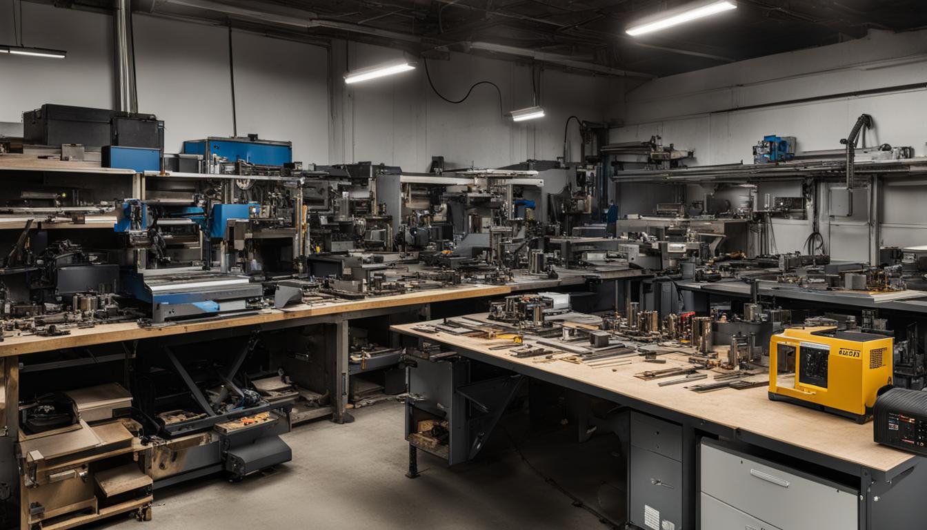
CNC conversion kits offer a practical pathway for upgrading traditional manual machine tools into automated, computer numerical control (CNC) systems. This transformation significantly enhances precision, repeatability, and the ability to produce complex geometries that are challenging or impossible with manual operation. Modern kits integrate advanced components, making the conversion process more accessible than ever before.
Retrofitting Manual Mills and Lathes
Retrofitting a manual mill or lathe involves systematically replacing or augmenting its mechanical and control elements to enable automated, computer-driven operation. This process breathes new life into robust, often underutilized, manual machines, extending their utility in contemporary manufacturing environments.
The primary motivation for such a conversion is to overcome the inherent limitations of manual machines, particularly the backlash present in traditional lead screw systems. Backlash, or ‘slop,’ in the lead screws compromises accuracy, especially when changing direction during machining operations like contouring or circular interpolation. Manual machines also struggle with the consistent production of intricate parts.
A comprehensive retrofit typically encompasses several key stages: mechanical upgrades to enhance motion precision, the installation of powerful stepper or servo motors, and the integration of sophisticated electronic control systems. This structured approach ensures that the converted machine can reliably execute complex G-code programs.
Key Components: Motors and Motion Control
| Feature | Stepper Motors | Servo Motors |
|---|---|---|
| Control System | Open-loop (typically) | Closed-loop with feedback |
| Precision | Good at low speeds, can lose steps under load | Exceptional, real-time error correction |
| Speed Range | Lower top speed (up to ~1000 RPM useful) | Higher top speed (up to 5000-8000 RPM) |
| Torque Characteristics | High holding torque, drops at higher speeds | Consistent torque across speed range |
| Cost | More economical | Higher initial investment |
| Complexity | Simpler to control | More complex tuning and control |
Motion control in a CNC converted machine relies heavily on the choice of motors, which translate electrical signals into precise mechanical movement along each axis. Both stepper and servo motors are viable options, each presenting distinct advantages for different application requirements and budgets.
Stepper motors operate in an open-loop system, moving in discrete, fixed angular steps without direct feedback on their actual position. They are generally more affordable and simpler to implement, providing high holding torque at low speeds. Common sizes like NEMA 23 (2.3 x 2.3 inches faceplate) and NEMA 34 (3.4 x 3.4 inches faceplate) are widely used, with NEMA 23 motors typically offering 2-3 Nm of holding torque and NEMA 34 motors delivering up to 12 Nm.
Servo motors, conversely, utilize a closed-loop system, incorporating an encoder that continuously monitors the motor’s position, speed, and torque. This feedback allows the controller to make real-time adjustments, ensuring exceptional accuracy, higher speeds, and consistent torque across their operating range.
Motor mounting brackets are crucial for securely attaching the chosen motors to the machine’s axes, ensuring proper alignment and rigidity. These brackets are often made from cast iron to minimize vibration and deflection, and they are specifically designed to accommodate standard NEMA frame sizes, such as NEMA 23 or NEMA 34, depending on the motor’s power and physical dimensions.
Precision Mechanics: Ball Screw Replacements
Replacing the original Acme lead screws with precision ball screws is a cornerstone of any effective CNC conversion. Ball screws are linear actuators that convert rotary motion into linear motion with significantly reduced friction and backlash compared to traditional lead screws. This mechanical upgrade is vital for achieving the accuracy and repeatability demanded by CNC machining.
The design of a ball screw incorporates recirculating ball bearings within a helical groove, facilitating smooth, low-friction movement. This design minimizes the ‘play’ that causes positional errors, allowing the machine to maintain precise tool paths and produce consistent parts. Double-nut ball screw designs further reduce backlash by preloading the nuts against each other.
Ball screw accuracy is classified by grades, typically C0 to C10, with lower numbers indicating higher precision. For CNC milling applications, a C5 grade is generally recommended, offering positional accuracy around ±0.001″-0.002″ over 12 inches of travel. While C7 grade screws are more economical, C5 provides the industrial standard for reliable precision.
Proper installation of ball screws requires careful attention to bearing support and preload. Using angular contact bearings on all axes maximizes rigidity and minimizes unwanted movement. Ensuring that bearing housings are made of steel, rather than aluminum, helps prevent preload drift due to thermal expansion differences between the screw and housing.
The Brains: Controller Board Electronics
The CNC controller board serves as the central processing unit for the converted machine, interpreting G-code commands from CAM software and translating them into precise step and direction pulses for the motors. This electronic heart dictates the machine’s overall performance, responsiveness, and capabilities.
Several popular controller platforms exist, each with its own ecosystem and features. GRBL-based boards are often favored for hobbyist and entry-level machines due to their open-source nature and simplicity. More advanced options include Mach3 and Mach4, which run on Windows, and LinuxCNC, known for its real-time performance on a Linux kernel. Industrial-grade solutions like MASSO and Centroid offer robust, integrated control systems.
Modern CNC conversion kits increasingly feature USB or Ethernet-based controllers, moving away from older parallel port interfaces. These newer interfaces provide greater reliability, lower latency, and better compatibility with contemporary PCs, enabling more stable and responsive motion control. Many controllers also include hardware-accelerated axis outputs for jitter-free pulse generation.
Beyond basic motion control, a capable controller board integrates various essential input/output (I/O) functions. These include connections for limit switches, emergency stop buttons, spindle speed control, coolant activation, and probing systems. The ability to expand these I/O capabilities is crucial for future machine enhancements and automation.
Converting a Bridgeport Mill to CNC
The Bridgeport Series I vertical knee mill is a perennial favorite for CNC conversion due to its robust cast-iron construction, widespread availability, and generous work envelope. Its inherent rigidity provides an excellent foundation for a high-performance CNC machine, capable of handling significant cutting forces.
Converting a Bridgeport involves specific mechanical considerations. The machine’s substantial weight, typically around 1,930 to 2,000 lbs for a Series I, necessitates careful planning for motor sizing and structural modifications. The original lead screws must be replaced with ball screws on all axes to eliminate backlash and achieve CNC-level precision.
Motor selection for a Bridgeport conversion often involves NEMA 23 stepper or servo motors for the X and Y axes, while the heavier Z-axis (knee or quill) frequently benefits from a more powerful NEMA 34 motor or a dedicated servo system. Proper gearing and pulley ratios are essential to match motor torque and speed to the machine’s mechanical requirements.
Controller options for Bridgeport conversions range from DIY-friendly LinuxCNC setups to more integrated industrial solutions like Centroid or ACU-RITE MillPWR G2 controls. These systems provide the necessary G-code interpretation, axis coordination, and I/O management to transform the manual mill into a fully functional, automated machining center.