
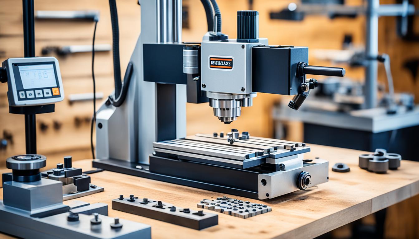
Acquiring a small milling machine represents a significant investment for any workshop, whether for hobbyist pursuits or professional prototyping. Careful consideration of technical specifications and operational requirements is essential to ensure the chosen machine aligns with specific project demands. This guide details critical factors for evaluating benchtop milling machines, from physical dimensions to control system options.
The market for compact milling machines has expanded considerably, with models capable of handling a wide range of materials and precision tasks. Understanding the nuances between different machine classes, such as mini mills and benchtop mills, is crucial for making an informed decision. These machines offer varying capabilities, impacting everything from workpiece size to achievable tolerances.
Benchtop Milling Machine Size and Capacity
Evaluating a benchtop milling machine’s physical size and work envelope is the foundational step in the selection process. Mini mills typically offer work areas around 8 x 6 x 10 inches, while benchtop models expand this to approximately 12 x 8 x 14 inches. This additional work envelope, often a 50% increase, significantly impacts the maximum workpiece dimensions and complexity of parts that can be machined.
Machine weight also correlates directly with stability and material capability. Mini mills generally weigh between 50 and 150 pounds, whereas benchtop mills range from 200 to 500 pounds. Heavier machines inherently provide better vibration dampening, which is critical for achieving finer surface finishes and maintaining tighter tolerances, especially when machining harder materials like steel.
A typical benchtop mill might feature a table size between 22 x 7 inches and 30 x 10 inches, with X-axis travel from 10 to 19.75 inches, Y-axis travel from 4 to 6.75 inches, and Z-axis travel (quill or headstock) around 3 to 9.75 inches. These dimensions dictate the practical limits of your machining projects. Always compare your largest anticipated workpiece against the machine’s stated travel before committing to a chassis size.
Motor Horsepower and Spindle Performance
| Feature | Manual Mill | DRO-Equipped Mill | CNC Mill |
|---|---|---|---|
| Control Method | Handwheels | Handwheels with Digital Display | Computer Program (G-code) |
| Typical Precision | Operator-dependent | ±0.001″ to ±0.002″ | ±0.001″ to ±0.002″ (standard) |
| Repeatability | Low to Moderate | Moderate to High | High |
| Complexity of Parts | Simple to Moderate | Moderate | High (3- to 5-axis contours) |
| Learning Curve | Moderate | Low | High |
| Cost (Relative) | Lowest | Medium | Highest |
Motor horsepower (HP) is a primary indicator of a small milling machine’s cutting power and its ability to handle various materials. Benchtop mills typically feature motors ranging from 0.5 HP to 3 HP. Higher horsepower allows for more aggressive cuts, larger tools, and the comfortable machining of tougher materials such as steel, which demands more torque, especially at lower spindle speeds.
Spindle speed, measured in revolutions per minute (RPM), is equally critical. Small mills offer variable speed ranges, commonly from 100 RPM up to 4,000 RPM, with some high-speed spindles reaching 10,000 RPM or even 20,000 RPM for specialized applications like micro-machining or working with softer materials. The ability to adjust spindle speed is vital for optimizing feeds and speeds, preventing tool breakage, and achieving desired surface finishes across different materials.
For instance, aluminum generally requires higher spindle speeds (8,000–12,000 RPM) and moderate feed rates, while mild steel necessitates lower speeds (around 100 SFM or 1000-2000 RPM for a 1/4″ endmill) and steady feeds. The spindle taper, such as R8 or ER16, determines the compatibility with various cutting tools and collet systems. An R8 taper is a dominant North American hobby-mill tooling standard.
Assessing Column Rigidity for Precision
Column rigidity is a paramount, yet often overlooked, factor influencing a small milling machine’s precision and surface finish. A flexible column can lead to chatter, poor dimensional accuracy, and reduced tool life, particularly during heavy cuts or when using boring heads. Many entry-level mini mills, especially those with tilting columns, are known to exhibit significant flex.
Manufacturers have addressed rigidity concerns by introducing solid, heavier column castings, sometimes increasing weight by over 60% compared to older designs. Aftermarket modifications, such as adding stiffening plates to the back of the column or filling the column with epoxy granite, are popular methods to enhance structural integrity and damp vibrations. These modifications aim to minimize deflection, which is crucial for maintaining consistent cutting forces and achieving tighter tolerances.
The connection between the column and the base is a common weak point, often supported by a narrow base or a single pivot bolt. A robust, wide mounting flange and sufficient wall thickness in the column casting are indicators of superior rigidity. Testing for deflection by applying gentle pressure to the head and observing a dial test indicator (DTI) can reveal inherent flex in a machine.
Manual vs DRO vs CNC Upgrade
Choosing the control system for a small milling machine involves weighing cost, complexity, and desired capabilities. Manual mills, operated entirely by handwheels, offer direct control and are often less expensive. They are ideal for one-off parts, prototyping, and learning fundamental machining skills, as adjustments can be made quickly without programming.
Digital Readouts (DROs) significantly enhance manual milling by providing real-time, precise positional feedback for each axis. DROs eliminate the need to count handwheel rotations, reducing human error and improving accuracy, typically to within ±0.001 to ±0.002 inches. They are a cost-effective upgrade that bridges the gap between purely manual operation and full computer control, offering ease of use with minimal learning time.
CNC (Computer Numerical Control) conversion transforms a manual mill into an automated system, reading G-code to control axis movements via stepper or servo motors. CNC machines excel at repeatability, complex geometries, and efficient production of multiple identical parts, often achieving typical tolerances of ±0.001 to ±0.002 inches, with precision applications reaching ±0.0005 inches on reamed holes. While requiring a greater investment in time and money for programming and setup, CNC offers unparalleled automation and precision for intricate designs.
Optimizing Your Workspace Footprint
Matching the milling machine’s footprint to your available workspace is a practical consideration that impacts workflow and safety. Benchtop mills, by definition, are designed for smaller spaces, but their actual ‘footprint’ extends beyond the base dimensions to include necessary clearance for operation, maintenance, and material handling. A typical benchtop mill might have a base footprint of 9.1 x 16.1 inches, but require a larger operational area.
Consider the machine’s overall dimensions, including height, width, and depth, especially with fully extended leadscrew covers or headstock movement. For example, a Rockwell 21-100, a mid-size floor mill often considered by hobbyists, stands 73.5 inches high, is 37.5 inches wide, and 33.75 inches deep, weighing around 780 pounds. Such machines require adequate ceiling height (minimum 80 inches) and doorway width (minimum 32 inches) for installation.
Ensure sufficient clearance around all sides of the machine to allow for full table travel, tool changes, chip evacuation, and access for maintenance or repairs. Positioning the machine at an angle to a wall can sometimes optimize space for long parts or table travels. Additionally, consider the optimal work height for the operator, which can be customized with a suitable stand or bench.
Power requirements are also part of the footprint consideration. Most small benchtop mills operate on standard 110V/120V single-phase power, but larger benchtop or mid-size floor mills may require 220V or even three-phase power. Adequate electrical circuits and safety disconnects are essential for any milling machine installation.