
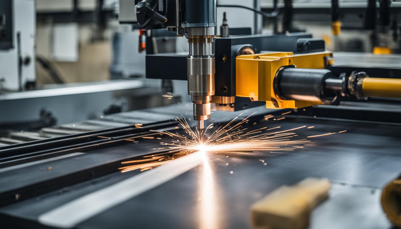
The CNC table serves as the foundational workholding platform for all computer numerical control machining operations. This critical component directly influences part accuracy, surface finish, and overall manufacturing efficiency. Its design and material composition are engineered to provide a stable, rigid interface between the workpiece and the machine’s cutting tools.
Understanding the CNC Table
A CNC table is more than just a flat surface; it is an integral part of the machine’s structural system, ensuring stability and precision throughout every operation. These tables are typically constructed from robust materials like heavy-duty steel or cast iron, chosen for their ability to dampen vibrations and maintain geometric accuracy under dynamic loads.
The table’s primary function involves securely holding the workpiece in a defined position, resisting the significant forces generated during cutting, milling, or drilling. This stability is paramount for achieving the tight tolerances and repeatable results demanded by modern manufacturing. Without a rigid and precise table, even the most advanced control systems and cutting tools cannot deliver optimal performance.
Modern CNC tables often integrate advanced features, including sophisticated workholding mechanisms and integrated feedback systems. These enhancements contribute to reduced setup times and improved process reliability, which are crucial for high-volume production environments. The table’s design must also accommodate various auxiliary systems, such as coolant delivery and chip evacuation.
Flat Bed Gantry Router Tables
| Feature | Honeycomb Bed | Slat Bed | Pin / Knife Bed |
|---|---|---|---|
| Material Support | Excellent for thin materials and small parts, even support. | Good for larger sheets, material rests on parallel blades. | Minimal contact points, good for thicker materials. |
| Airflow & Fume Dissipation | Optimized airflow, reduces smoke and heat. | Good airflow under material. | Allows good airflow, minimal contact. |
| Back-Reflection | Reduces reflections as laser falls into cells. | Minimizes ‘flashback’ marks due to minimal contact. | Reduces contact with bed, minimizes marks. |
| Maintenance & Cleaning | Soot, resin, debris accumulate quickly; harder to clean. | Easier to clean than honeycomb. | Relatively easy to clean, less debris accumulation. |
| Typical Applications | Engraving, paper, plywood, fabrics, thin acrylic, delicate parts. | Cutting larger sheets, general purpose. | Thicker acrylic, materials where underside marks are critical. |
Flat bed gantry router tables are characterized by a stationary workpiece bed and a moving gantry that carries the spindle and cutting head. This configuration is widely used for processing large sheets of material, including wood, plastics, composites, and aluminum. The bed itself must possess exceptional flatness and rigidity to support the material uniformly and prevent deflection during machining.
Typical flatness tolerances for high-precision gantry router beds are extremely tight, often measured in thousandths of an inch or hundredths of a millimeter across the entire working surface. Maintaining this flatness is essential for consistent depth of cut and accurate part geometry, particularly when machining thin sheet materials. The structural integrity of the bed is often reinforced with internal ribbing or a honeycomb core.
Feeds and speeds for gantry routers vary significantly based on material and tool geometry. For instance, machining 6061 aluminum with a carbide end mill typically involves spindle speeds between 8,000 and 12,000 RPM, with feed rates ranging from 40 to 80 inches per minute (IPM). A chip load of 0.001–0.003 inch per tooth is common for a 2-flute end mill.
When routing dense hardwoods like walnut, recommended spindle speeds are generally lower, around 6,000–8,000 RPM, with feed rates of 60–100 IPM. Carbon fiber, conversely, benefits from higher RPMs (12,000–18,000) but slower feed rates (30–60 IPM) to prevent fraying. Plunge rates are also critical, with 800 mm/min for timber and plastic, and 400 mm/min for aluminum being common starting points.
Plasma and Laser Cutting Beds
Plasma and laser cutting beds are specialized tables designed to withstand the intense heat and byproducts of thermal cutting processes. These beds must facilitate efficient fume extraction and slag removal while providing stable support for the material. Fume extraction systems are crucial for capturing ultrafine metallic oxides and other hazardous particles generated during cutting, which can damage equipment optics and pose health risks.
Laser cutting beds come in several configurations, each optimized for different materials and applications. Honeycomb beds, often made from aluminum or steel, offer excellent support for thin materials and small parts, reducing back-reflection and promoting airflow for smoke dissipation. However, they can accumulate soot and debris, requiring regular cleaning.
Slat beds, composed of parallel metal blades, are well-suited for cutting larger sheets and are easier to clean than honeycomb designs. Pin or knife beds minimize contact with the material, reducing marks on the underside, and are particularly effective for thicker acrylic. Proper maintenance, including cleaning and checking for levelness, is vital for all laser bed types.
Plasma cutting tables frequently incorporate downdraft systems or water tables to manage fumes and slag. Downdraft tables use zoned extraction to concentrate suction directly beneath the cutting head, while water tables submerge the workpiece to absorb heat and trap particulates. Automated slag removal systems, utilizing hardened steel pins or grinding, are increasingly common to efficiently clean the support slats.
Vacuum Hold-Down Table Systems
Vacuum hold-down tables secure workpieces by creating a pressure differential between the vacuum beneath the material and the atmospheric pressure above it. This method eliminates the need for mechanical clamps, providing an unobstructed work surface and significantly reducing setup times. It is particularly advantageous for flat sheet materials and repeat production.
Key components of a vacuum table include the plenum (work surface with grooves or holes), a gasket system to create airtight zones, and a vacuum pump or blower. Optional bleeder boards, often made of porous MDF, help distribute the vacuum and protect the plenum from deep cuts.
Various vacuum pump technologies are employed, each with distinct characteristics. Rotary vane pumps deliver high vacuum levels and strong holding force, making them suitable for dry machining of non-porous materials like wood, plastic, and aluminum. Regenerative blowers, or side-channel blowers, offer high airflow at lower vacuum levels, ideal for porous materials like MDF spoilboards where constant leakage is expected.
Claw pumps provide a balance of high vacuum and strong performance, handling both porous sheet work and jig-based tasks. Typical effective clamping occurs at vacuum levels between -0.7 and -0.9 bar (-10 to -13 PSI), with standard figures often between 0.6 to 0.8 bar (8.7 to 11.6 PSI). Holding force is directly proportional to the contact area and the differential pressure.
Sheet Material Positioning and Clamping
Accurate sheet material positioning is fundamental for achieving consistent part quality and optimizing material yield in CNC operations. Precision alignment systems ensure that each sheet is placed identically, minimizing errors and reducing waste. This is especially critical in high-volume manufacturing where even minor discrepancies can lead to significant material loss.
Pin registration systems are a common method for repeatable sheet positioning. These systems use precisely machined pins that engage with corresponding holes in the workpiece or a sub-plate, ensuring exact alignment every time. Automated loading systems often integrate these pins to streamline the material handling process, reducing manual intervention and improving cycle times.
Edge alignment systems, which use sensors or mechanical stops to square the material against a datum, also contribute to precise placement. The combination of robust positioning and secure clamping is essential to counteract cutting forces and maintain workpiece stability throughout the machining cycle. Modern practices emphasize quick-change fixturing to maximize machine uptime.
Workpiece Clamping Surfaces
The workpiece clamping surface is the direct interface between the machine table and the material, and its design significantly impacts workholding versatility and efficiency. T-slot tables are a ubiquitous solution, featuring a grid of T-shaped channels that allow for flexible positioning of clamps, vises, and fixtures. This adaptability makes them suitable for a wide range of part sizes and geometries.
Modular clamping systems represent a significant advancement, utilizing standardized grid plates with precision-located threaded holes. These systems, often incorporating zero-point clamping technology, allow for rapid reconfiguration of clamps, stops, and supports. Repeatability of less than 0.002 mm is achievable with advanced zero-point systems, drastically reducing setup times for diverse jobs.
Beyond T-slots and modular systems, various mechanical clamps are employed. Strap clamps are versatile, bridging the workpiece surface and applying force via a stud. Toe clamps engage the edge of the workpiece, leaving the top surface clear for machining, while edge clamps combine location and clamping in one element. Magnetic clamping systems offer another option, generating holding force through the workpiece material itself, particularly useful for ferrous metals.
The selection of a clamping surface and method depends on the workpiece material, geometry, required machining access, and production volume. Modern engineering practices prioritize systems that offer both high clamping force and quick, repeatable setup to maximize machine utilization and overall productivity.