
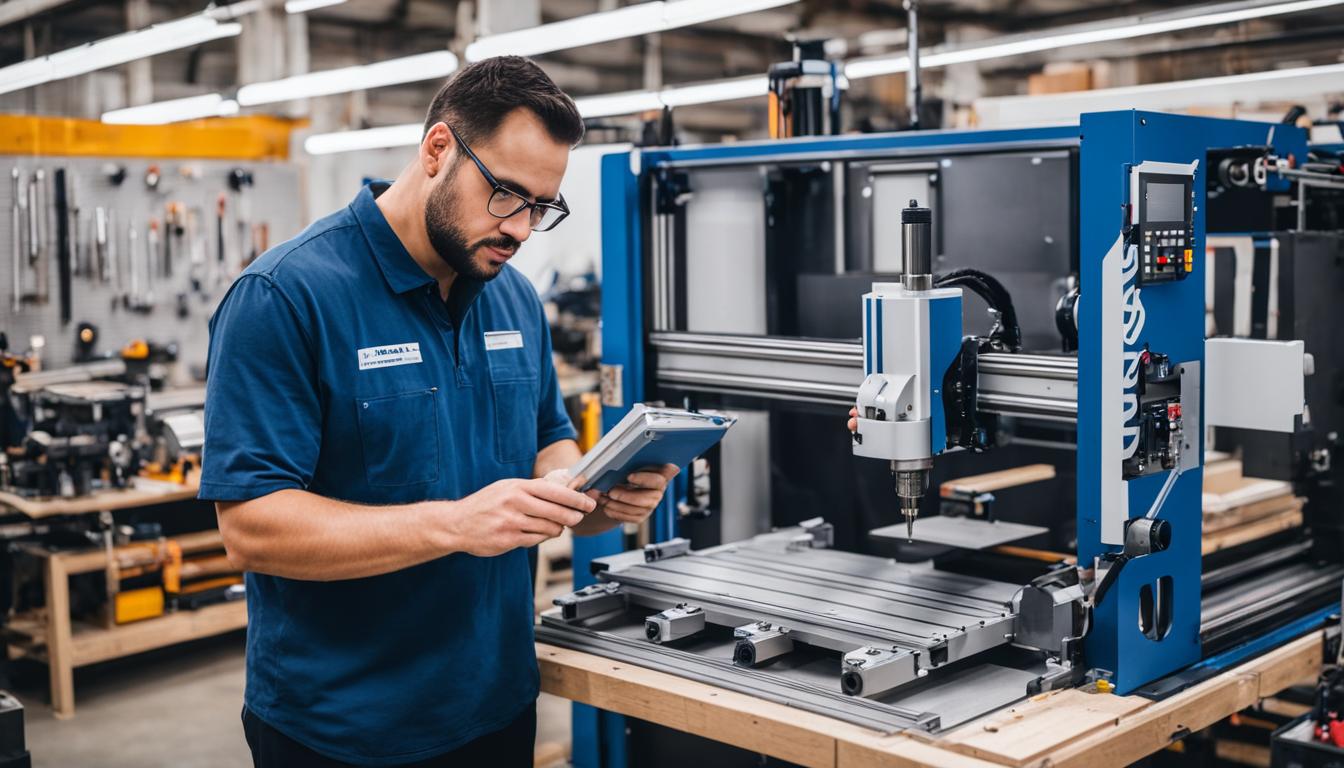
Constructing a personal Computer Numerical Control (CNC) machine offers significant advantages for hobbyists and small workshops seeking precise automated fabrication. This endeavor requires a foundational understanding of mechanical, electrical, and software integration. A well-planned DIY build can provide a cost-effective solution for custom manufacturing tasks.
DIY CNC Kit Assembly Considerations
Assembling a DIY CNC kit streamlines the construction process by providing pre-engineered components and detailed instructions. These kits typically include the frame, stepper motors, a controller board, and often a spindle, reducing the complexity of sourcing individual parts. Opting for a reputable kit manufacturer ensures component compatibility and often includes comprehensive support resources.
Successful kit assembly hinges on meticulous attention to detail and adherence to the manufacturer’s guidelines. Proper tool selection, such as precision wrenches, hex key sets, and a multimeter, is essential for accurate and secure component installation. Verifying all fasteners are torqued correctly prevents future mechanical issues and ensures machine rigidity.
Initial calibration steps, often involving squaring the frame and checking for perpendicularity of axes, are critical for achieving accurate machining results. Many kits provide jigs or specific procedures to aid in these adjustments, ensuring the machine operates within its design tolerances. Skipping these foundational steps can lead to cumulative errors in finished parts.
Sourcing Precision Linear Motion Components
| Component Type | Typical Precision Grade (Hobby) | Positional Accuracy (per 300mm) | Key Benefit |
|---|---|---|---|
| Rolled Ball Screw | C7 | ±50 µm | Cost-effective, good for general purpose |
| Profile Linear Rail | H/P (High/Precision) | ±20 µm | High rigidity, load capacity |
Precision linear motion components are fundamental to a CNC machine’s accuracy and repeatability. Profile linear rails, such as those from Hiwin’s HG or EG series, are widely favored for their high load capacity and rigidity, offering superior performance compared to unsupported round rails. These rails typically feature hardened steel construction and recirculating ball bearings for smooth, low-friction movement.
Ball screws translate rotary motion from stepper motors into precise linear motion. Rolled ball screws, commonly available in C7 precision grades, offer a good balance of cost and accuracy for hobbyist machines, typically exhibiting a positional accuracy of ±50 micrometers per 300mm. Ground ball screws (C5 or C3 grades) provide higher precision but at a significantly increased cost, often reserved for professional-grade equipment.
Minimizing backlash in ball screw assemblies is crucial for dimensional accuracy, especially during direction changes. Anti-backlash nuts are a common solution, employing a spring-loaded mechanism to maintain constant contact between the nut and the ball screw threads. Proper mounting and alignment of these components prevent binding and premature wear.
Wiring Stepper Motors and Drivers
Stepper motors are the workhorses of DIY CNC machines, converting electrical pulses into discrete mechanical steps. Common sizes include NEMA 17 for lighter loads, NEMA 23 for most hobbyist routers, and NEMA 34 for larger, more powerful machines requiring higher torque. Selecting motors with appropriate torque ratings for your machine’s axis weight and cutting forces is paramount.
Stepper motor drivers regulate the current supplied to the motor coils, enabling microstepping for smoother motion and reduced resonance. Drivers like the TB6600 or DM542 are popular choices, offering adjustable current settings and microstep resolutions up to 1/32 or 1/64 steps. Correctly setting the driver’s current limit prevents motor overheating and ensures optimal performance.
Wiring involves connecting the motor coils to the driver and the driver to the controller. Most stepper motors are bipolar, requiring four wires (two pairs) connected to the driver’s A+, A-, B+, B- terminals. Proper shielding of motor cables minimizes electrical noise, which can interfere with controller signals and lead to missed steps or erratic behavior. A dedicated power supply, typically 24V to 48V DC, is required to power the drivers and motors.
Configuring GRBL/Arduino Controllers
GRBL is an open-source, high-performance G-code parser and CNC milling controller that runs on an Arduino Uno microcontroller. Its simplicity and robust feature set make it an ideal choice for DIY CNC projects. Flashing the GRBL firmware onto an Arduino Uno is typically done using the Arduino IDE or a dedicated flashing tool, ensuring the latest stable version is installed.
Connecting the GRBL-enabled Arduino to stepper motor drivers, limit switches, and spindle control relays forms the core of the machine’s electronics. Limit switches, wired in series, provide safety by preventing axes from crashing into their physical limits. Spindle control often involves a relay triggered by the Arduino’s digital output, allowing G-code to turn the spindle on and off.
Configuring GRBL parameters is essential for matching the software’s motion control to your machine’s physical characteristics. Key settings include ‘$100’, ‘$101’, ‘$102’ for steps per millimeter for the X, Y, and Z axes, respectively. Other critical parameters like ‘$110’, ‘$111’, ‘$112’ (max speed) and ‘$120’, ‘$121’, ‘$122’ (acceleration) must be tuned to prevent motor stalling and ensure smooth operation.
Custom Frame Construction
The frame is the backbone of any CNC machine, dictating its rigidity, accuracy, and overall performance. Aluminum extrusion, such as 80/20 profiles, is a popular choice for DIY frames due to its modularity, ease of assembly, and good strength-to-weight ratio. Steel tubing, either welded or bolted, offers superior rigidity for heavier-duty applications but requires more specialized fabrication skills.
Design considerations for a custom frame include the desired work envelope, gantry type (moving gantry or moving table), and the anticipated cutting forces. A robust design minimizes deflection and vibration, which are detrimental to surface finish and dimensional accuracy. Finite Element Analysis (FEA) software can be used to optimize frame designs, though simpler beam deflection calculations suffice for many hobby builds.
Assembly methods for custom frames vary by material. Aluminum extrusions are typically joined with T-nuts and specialized brackets, allowing for easy adjustments and modifications. Steel frames often require welding for maximum rigidity, followed by stress relieving and precision machining of mounting surfaces. Regardless of the material, ensuring the frame is perfectly square and level during assembly is paramount for accurate axis alignment.