
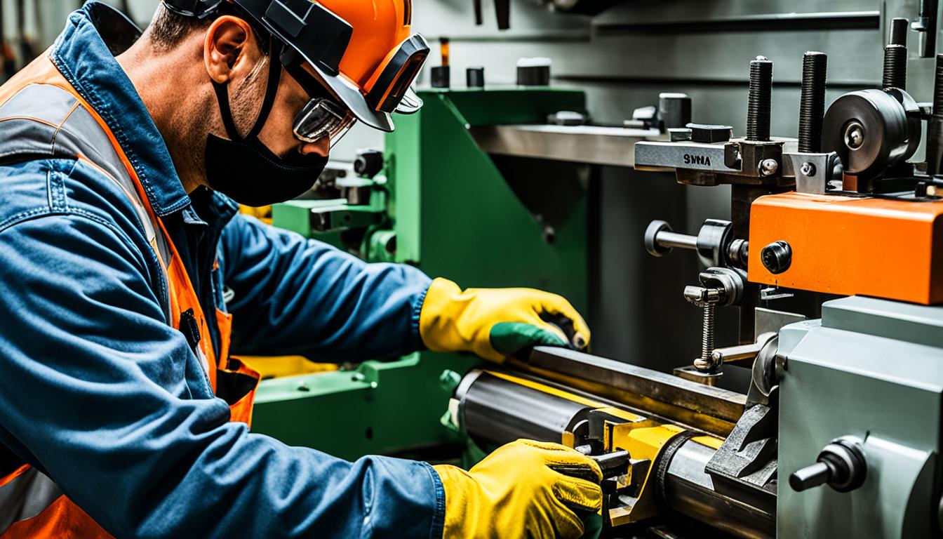
Operating a lathe machine demands a meticulous approach to safety and precision, ensuring both operator well-being and the quality of machined components. Modern turning operations, whether manual or CNC, rely on fundamental engineering principles and strict adherence to established protocols. Understanding these core practices is paramount for any tooling engineer or machinist.
Workholding Security: Chuck Mounting and Inspection
Securely mounting the workpiece in a lathe chuck is the foundational step for any turning operation, directly impacting accuracy, rigidity, and operator safety. Improper workholding can lead to workpiece ejection, tool chatter, and significant dimensional errors. Always select the appropriate chuck type for the job, such as a three-jaw self-centering chuck for round stock or a four-jaw independent chuck for irregular shapes.
Before mounting, thoroughly inspect the chuck jaws for wear, damage, or embedded chips, which can compromise gripping force and concentricity. Clean any debris from the chuck’s bore and the workpiece contact surfaces. Ensure the chuck is properly seated and securely tightened onto the lathe spindle, never using machine power for installation or removal.
After securing the workpiece, immediately remove the chuck key or wrench from the chuck. A chuck key left in a rotating chuck can be ejected with lethal force, posing an extreme hazard. Verify the workpiece is firmly gripped and has adequate clearance to rotate freely without contacting the machine bed, carriage, or tool post.
For longer workpieces, additional support from a tailstock center or steady rest is often necessary to prevent deflection and vibration during cutting. Regularly inspect these auxiliary workholding devices for proper function and secure clamping to the lathe bed. Lubricate contact points between steady rest jaws and the workpiece to minimize friction.
Precision Tool Setup: Achieving Correct Center Height
| Material | Tool Material | Cutting Speed (SFM) | Roughing Feed (IPR) | Finishing Feed (IPR) |
|---|---|---|---|---|
| Aluminum (6061) | Carbide | 600-1200 | 0.004-0.010 | 0.002-0.005 |
| Mild Steel | HSS | 60-100 | 0.005-0.015 | 0.002-0.005 |
| Stainless Steel | HSS | 40-50 | 0.002-0.005 | 0.001-0.003 |
| Brass | HSS | 80-150 | 0.005-0.015 | 0.002-0.005 |
| Engineering Plastics | HSS | 200-400 | 0.004-0.010 | 0.002-0.004 |
Accurate tool center height alignment is critical for optimal cutting performance, surface finish, and tool life in lathe operations. When the tool tip is precisely on the spindle’s center axis, cutting forces are evenly distributed, promoting stable chip formation and preventing issues like chatter or rubbing.
An incorrectly set tool height can lead to several problems. If the tool is too high, it may cut above the center, causing the workpiece to ‘climb’ over the tool or resulting in a poor finish. Conversely, if the tool is too low, it can contact the workpiece at a negative angle, leading to rubbing, excessive tool wear, and potential damage to the insert or tool.
Several methods exist for achieving precise center height. A common technique involves using a center gauge, aligning its V-shaped notch over the tool’s cutting edge and its flat surface with the workpiece centerline. Another effective method utilizes a center drill chucked in the headstock, allowing the tool bit’s tip to be raised or lowered until it aligns with the center drill’s tip.
For fine-tuning, a dial indicator or a precision ruler can be employed. Placing a rigid machinist’s ruler between the tool and the workpiece and adjusting the tool’s height until the ruler is perfectly perpendicular to the spindle axis provides a reliable visual check. Modern CNC lathes often use tool offset parameters for precise digital adjustment.
Optimizing Machining Performance: Feeds and Speeds Selection
Selecting appropriate feeds and speeds is fundamental to efficient material removal, achieving desired surface finishes, and extending tool life. These parameters are influenced by several factors, including workpiece material, cutting tool material and geometry, machine rigidity, and the required depth of cut.
Cutting speed, typically expressed in Surface Feet per Minute (SFM) or meters per minute (m/min), represents the speed at which the cutting edge moves relative to the workpiece. Spindle speed (RPM) is then calculated based on the cutting speed and the workpiece diameter. Higher cutting speeds are generally suitable for softer materials like aluminum, while harder materials require slower speeds.
Feed rate, measured in Inches Per Revolution (IPR) or Inches Per Minute (IPM), dictates how quickly the tool advances through the material. Roughing operations typically use heavier feeds and deeper cuts for rapid material removal, whereas finishing passes require lighter feeds and shallower depths of cut to achieve a smooth surface finish.
Carbide tooling generally permits significantly higher cutting speeds and feed rates compared to High-Speed Steel (HSS) tools due to its superior hardness and heat resistance. Always consult manufacturer recommendations and material-specific charts as a starting point, then adjust based on chip formation, surface finish, and tool wear.
Critical Operator Safety: Attire and Emergency Protocols
Operator safety on a lathe is paramount, with strict adherence to personal protective equipment (PPE) and machine protocols being non-negotiable. Rotating machinery presents severe entanglement hazards, making loose clothing, long hair, and jewelry extremely dangerous. These items can be caught and pulled into the machine, leading to severe injury or fatality.
Mandatory shop attire includes safety glasses or a face shield to protect against flying chips and coolant, and closed-toe shoes for foot protection. Long hair must be tied back or contained under a cap, and all jewelry, including rings, watches, and necklaces, must be removed. Gloves are generally prohibited when operating a lathe due to the risk of entanglement.
Familiarity with the machine’s emergency stop (E-stop) locations is crucial for all operators. E-stop buttons are designed to be easily identified and actuated, typically featuring a red mushroom-head button on a yellow background. These devices must be readily accessible from all operator control stations and any identified hazard zones.
Emergency stop devices should be positioned between 0.6 meters and 1.7 meters above the access level for hand actuation, ensuring quick and unobstructed access. They are typically self-latching, requiring a manual reset after activation, and should never be bypassed or tampered with. Regular training on E-stop procedures and lockout/tagout protocols is essential for a safe working environment.
Understanding Lathe Tolerances and Modern Practices
Achieving specified tolerances is a hallmark of precision machining, directly influencing part functionality and assembly. Standard commercial tolerances for CNC turning typically range around ±0.005 inches (±0.13 mm) on general diameter features. Most competent machine shops can consistently hold these tolerances for routine work in common materials like aluminum and mild steel.
For critical dimensions requiring higher precision, tolerances of ±0.002 inches (±0.05 mm) are achievable with proper tooling, rigid workholding, and a controlled machining environment. Ultra-tight tolerances, such as ±0.001 inches (±0.025 mm) or even tighter, demand slower finishing passes, exceptionally sharp tooling, and meticulous temperature stability.
Material properties significantly influence achievable tolerances. Metal parts generally allow tighter tolerances than plastics due to their greater dimensional stability. Aluminum alloys, for instance, offer excellent machinability, often allowing for tolerances of ±0.05 mm, while engineering plastics may require wider tolerances, typically ±0.15 mm to ±0.25 mm, due to thermal sensitivity and flexibility.
Modern engineering practices emphasize specifying tight tolerances only where functionally necessary, as tighter tolerances exponentially increase machining costs due to longer cycle times, specialized equipment, and more intensive inspection. Geometric Dimensioning and Tolerancing (GD&T) provides a comprehensive system for controlling part geometry, ensuring accuracy and precision in complex designs.