
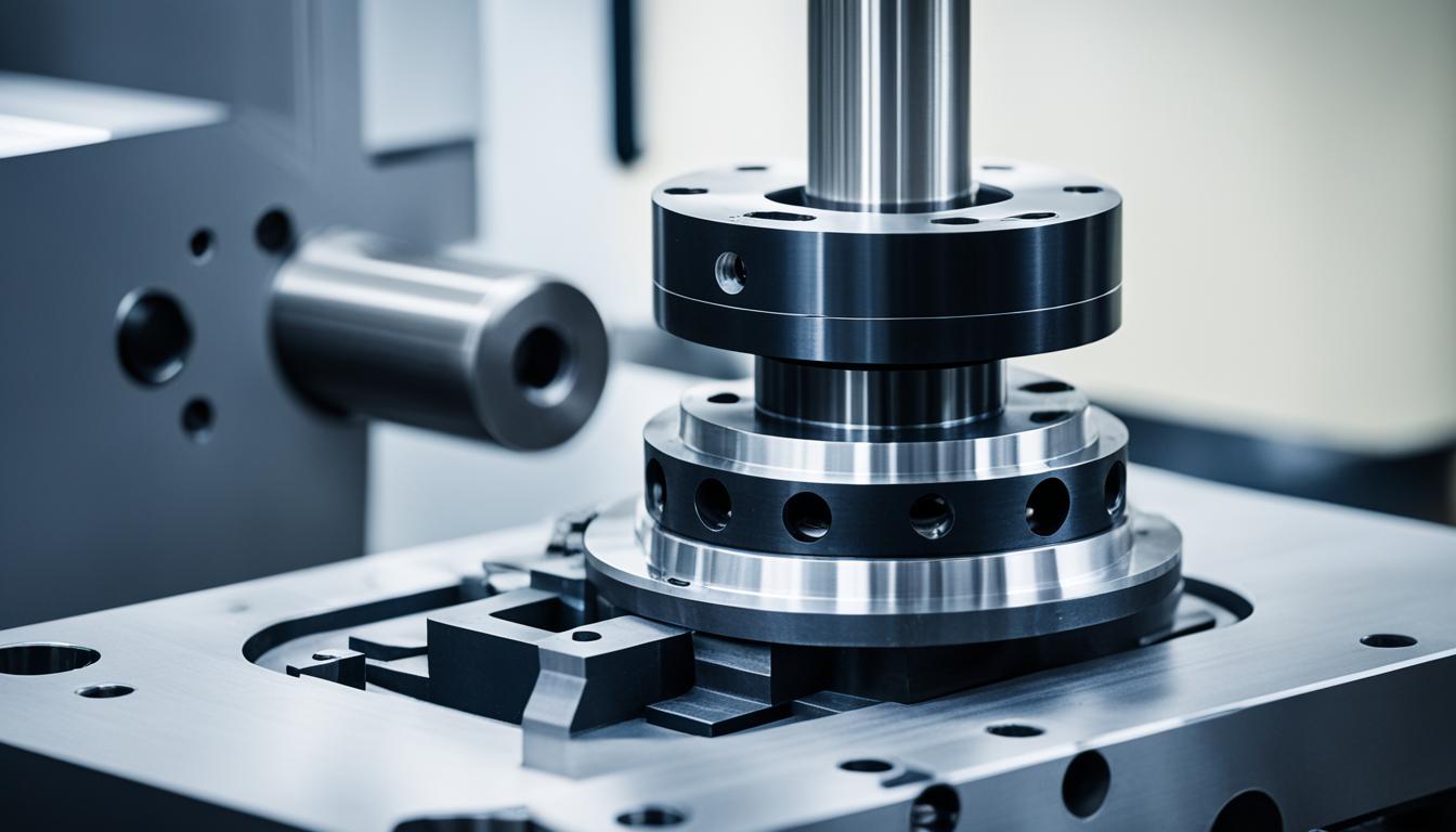
Precision manufacturing relies heavily on the inherent capabilities of Computer Numerical Control (CNC) machines. Key design and operational features directly influence a machine’s ability to produce accurate, repeatable, and high-quality components efficiently. Understanding these critical elements is fundamental for any tooling engineer optimizing production workflows.
Machine Frame Rigidity
The structural integrity of a CNC machine’s frame is paramount, directly impacting machining accuracy and surface finish. A rigid frame resists deflection under cutting forces, preventing chatter and maintaining dimensional precision throughout the machining process. Materials like cast iron are favored for their high density and stiffness, which naturally dampen vibrations.
Polymer concrete bases, often found in high-end CNC machines, offer exceptional vibration absorption and thermal stability. While welded steel frames are lighter, they typically require additional dampening features to compensate for their lower inherent stability.
Damping characteristics are as crucial as stiffness. Damping refers to the system’s ability to dissipate energy during vibration, converting mechanical energy into heat. Insufficient damping leads to tool vibrations, surface ripple, and dimensional errors, ultimately reducing tool lifespan.
Static and dynamic rigidity targets vary significantly based on the material being machined. For instance, wood and plastics can be acceptably machined at 5 N/µm of static rigidity, whereas aluminum requires 10–20 N/µm. Machining steel typically demands 25 N/µm or higher to ensure optimal performance.
Controller Processing Speed
| Tolerance Type | Typical Range (inches) | Typical Range (mm) | Application |
|---|---|---|---|
| General Standard | ±0.005″ | ±0.127 mm | Prototypes, non-critical features |
| High Precision | ±0.001″ to ±0.002″ | ±0.025 mm to ±0.051 mm | Tight fits, critical features |
| Ultra-Precision | ±0.0001″ to ±0.0005″ | ±0.0025 mm to ±0.012 mm | Medical, aerospace, grinding, wire EDM |
| Angular Tolerance | ±0.5° (general) | ±0.5° (general) | General machining |
The CNC controller functions as the machine’s brain, translating G-code commands into precise mechanical movements. Its processing speed and algorithmic sophistication are critical for achieving high accuracy, contouring performance, and repeatability, especially in complex machining operations.
Modern controllers incorporate advanced ‘look-ahead’ algorithms, which pre-calculate the velocity profile for upcoming toolpaths by reading hundreds or even thousands of blocks ahead. This capability allows the machine to maintain a constant feed rate through directional changes without stopping, significantly improving surface finish and reducing cycle times by up to 30% on intricate geometries.
Such advanced motion control systems inherently create smoother motion, eliminating the abrupt stopping and jerking often associated with high-speed machining. This not only enhances part quality but also prolongs the life and accuracy of internal machine components like ballscrews and linear guides.
Spindle Power and Torque
Spindle power and torque are fundamental to a CNC machine’s material removal capabilities. Power, defined as work per unit of time, is directly related to torque and rotational velocity. Understanding the spindle’s torque-versus-RPM curve is essential for optimizing cutting parameters.
A typical spindle torque curve exhibits a constant-torque region at lower RPMs, where torque is maximized and horsepower rises linearly. This region is ideal for heavy roughing, tapping, and machining low-surface-feet-per-minute (SFM) materials like Inconel or titanium. As RPM increases, the spindle transitions into a constant-horsepower region, where torque inversely falls with speed, suitable for finishing and small-diameter tools requiring high SFM.
Machine tool builders often specify both continuous and peak horsepower (HP) or torque ratings. Continuous ratings indicate the power the spindle can sustain indefinitely, while peak ratings are for limited durations. Overrunning a spindle beyond its continuous rating can lead to overheating and potential damage, necessitating careful consideration of duty cycles.
For example, a 25 HP peak / 10 HP continuous spindle roughing 6061 aluminum at 100% load can sustain approximately 100–110 cubic inches per minute. However, a ’25 HP peak’ spindle might have significantly less low-RPM torque, making it unsuitable for demanding cuts despite its higher peak HP claim.
Linear Guide Encoder Precision
Linear encoders are critical for achieving high-precision positioning in CNC machines by providing real-time feedback on linear axis movement. These sensors directly measure position without mechanical elements like ball screws, eliminating potential error sources such as backlash and pitch error.
Encoder performance is characterized by resolution, accuracy, and repeatability. Resolution defines the smallest detectable movement, typically expressed in micrometers (µm) or nanometers (nm). Accuracy describes how closely the reported position matches the actual physical position, often stated as ±µm per meter. Repeatability indicates how consistently the machine returns to the same point.
Two primary types of linear encoders exist: incremental and absolute. Incremental encoders provide information about changes in position relative to a reference point, requiring a homing sequence upon power-up. Absolute encoders, conversely, provide a unique position value for every possible position, retaining data even after power loss, which is crucial for safety-critical applications.
Optical linear encoders are highly accurate and offer high resolution but can be sensitive to dust. Inductive encoders are more resistant to environmental contaminants but may be susceptible to electrical interference. The choice of encoder type and its specifications directly influences the machine’s ability to achieve sub-micron accuracy in demanding applications.
Automatic Tool Changer (ATC)
Automatic Tool Changers (ATCs) are indispensable for modern CNC manufacturing, dramatically increasing efficiency by eliminating manual tool changes. ATCs reduce cycle times by 30-50%, enabling lights-out manufacturing and significantly boosting productivity.
There are two main types of ATCs: linear and carousel. Linear ATCs, which can be fixed or follow-up, typically require the spindle to travel across the table to retrieve tools, resulting in change times of 8–20 seconds. Follow-up linear systems reduce this by keeping tools closer to the spindle.
Carousel changers are generally faster, often completing a tool change in 3–5 seconds, as they are mounted directly to the gantry or spindle assembly. Some high-performance ATCs, particularly those with dual-gripper designs and servo motors for precise magazine positioning, can achieve tool-to-tool times as fast as 0.8 seconds.
Optimizing ATC performance involves strategic tool arrangement in the magazine to minimize travel distance and utilizing parallel operations, such as spindle pre-rotation or coolant flushing, during tool changes. Programming instructions like M19 can orient the spindle during motion to the tool change position, further reducing non-productive time.
Standard CNC Machining Tolerances
Achievable tolerances are a critical consideration in CNC machining, directly impacting part functionality and cost. Standard tolerances are suitable for most general-purpose parts, while tighter tolerances demand more sophisticated equipment and processes.