
Precision threading is a fundamental process in modern manufacturing, enabling the assembly of components across countless industries. Engineers must possess a deep understanding of thread specifications, manufacturing methods, and critical design elements to ensure optimal performance and reliability. Selecting the correct thread standard and production technique directly impacts part functionality and cost-effectiveness.
This comprehensive guide explores the essential technical aspects of threads, from international standards to machining practices and critical design features. Adhering to established guidelines and leveraging advanced tooling ensures robust and interchangeable threaded connections in any application.
Metric vs. Unified Thread Pitch Standards
Global manufacturing primarily relies on two distinct thread standards: the ISO Metric Thread and the Unified Thread Standard (UTS). Both systems feature a symmetrical V-shaped thread profile with a 60° flank angle, ensuring geometric similarity.
The fundamental difference lies in their measurement systems and pitch specification. ISO Metric threads, designated by an ‘M’ followed by the nominal diameter and pitch in millimeters, are the most widely used worldwide. For example, ‘M10 x 1.5’ indicates a 10mm major diameter with a 1.5mm pitch.
Unified Thread Standard (UTS) threads, prevalent in the United States and Canada, specify dimensions in inches. Their pitch is defined as threads per inch (TPI). Common UTS series include Unified National Coarse (UNC) for general applications and Unified National Fine (UNF) for precision and vibration resistance.
Understanding these distinctions is crucial for international compatibility and proper fastener selection. While their profiles are similar, direct interchangeability is impossible due to differing measurement units and pitch values.
Tapping vs. Thread Milling for Precision
| Standard | Class | Fit Description | Application |
|---|---|---|---|
| Unified (ASME B1.1) | 1A (External) / 1B (Internal) | Loose fit | Easy assembly, dirty environments |
| Unified (ASME B1.1) | 2A (External) / 2B (Internal) | General purpose, free fit | Most common, balances strength and assembly |
| Unified (ASME B1.1) | 3A (External) / 3B (Internal) | Close fit | High precision, minimal play |
| Metric (ISO 965) | 6g (External) / 6H (Internal) | Standard fit | General purpose, comparable to 2A/2B |
| Metric (ISO 965) | 4g6g (External) / 5H (Internal) | Tighter fit | Precision applications, reduced mechanical play |
Creating threads in a workpiece typically involves either tapping or thread milling, each with distinct advantages and ideal applications. Tapping is a traditional method that uses a hardened cutting tool, a tap, to cut internal threads into a pre-drilled hole.
Tapping is generally faster for high-volume production of standard thread sizes and is often more economical for fewer threads. However, taps are specific to one thread size and pitch, requiring a different tool for each variation.
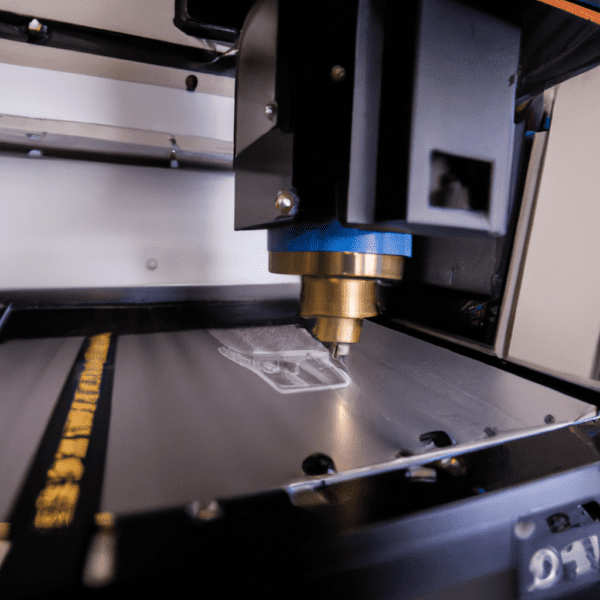
Thread milling employs a rotating thread mill tool guided by a CNC machine to cut threads using helical interpolation. This method offers superior control over thread size and fit, making it ideal for custom threads, tough materials like titanium or hardened steel, and large diameters.
Thread milling provides longer tool life, better chip control, and reduced risk of tool breakage compared to tapping, especially in blind holes or hard materials. While it may require more complex programming and setup, its versatility and precision often outweigh the slower cycle times for high-value parts.
Thread Class Tolerances and Fit
Thread class tolerances define the permissible variations in thread dimensions, dictating the tightness or looseness of fit between mating components. These classes are critical for ensuring proper assembly, load distribution, and fastener performance. Both Metric and Unified standards have their own classification systems.
For Unified Inch Screw Threads (ASME B1.1), classes are designated with a number and a letter (e.g., 2A, 2B). The number indicates the tolerance grade, while ‘A’ denotes external threads and ‘B’ denotes internal threads.
Metric fasteners use an alphanumeric system (ISO 965) where a number indicates the tolerance grade and a letter indicates the tolerance position. Lowercase letters (e.g., ‘6g’) apply to external threads, and uppercase letters (e.g., ‘6H’) apply to internal threads.
A tighter tolerance class, such as 3A/3B for Unified or 4g6g/5H for Metric, indicates a closer fit, often required for high-precision applications like aerospace or medical devices. Conversely, looser fits (e.g., 1A/1B or 6g/6H) allow for easier assembly, even with slight thread damage or in dirty environments.
External vs. Internal Threading Techniques
Manufacturing threads involves distinct approaches for external (male) and internal (female) features, often utilizing different machinery and tooling. External threading creates threads on the outer surface of a cylindrical workpiece, commonly seen in screws, bolts, and studs.
CNC lathes are frequently used for external threading, employing single-point threading tools that gradually form the thread profile over multiple passes. This method offers high accuracy and is suitable for custom or specialized threads.
Internal threading, conversely, involves cutting threads inside a pre-drilled hole or bore. This is essential for nuts, tapped holes, and threaded inserts. Common methods include tapping, which is fast for standard sizes, and thread milling, which provides greater flexibility and precision for complex or large-diameter internal threads.
For both internal and external threads, precise control over feed rate, cutting depth, and tool engagement is paramount to achieve dimensional accuracy and surface quality. Modern CNC machines can perform both operations with high repeatability, ensuring consistent thread quality across production runs.
The Critical Role of Chamfer Thread Entry
A chamfer at the thread entry is a small, angled surface that replaces a sharp 90° corner, serving several vital functions in manufacturing and assembly. This seemingly minor detail significantly impacts the ease of assembly, thread protection, and overall part quality.
The primary purpose of a chamfer is to guide the mating fastener smoothly into the thread, preventing cross-threading and reducing assembly time. It also protects the first thread from damage during handling or assembly, enhancing the durability of the threaded connection.
Standard practice often calls for a 45° chamfer, with its diameter slightly larger than the screw’s major diameter. For metric threads, a 45° x 0.5mm chamfer is common for M6-M10 sizes, or a chamfer equal to one pitch (1P) can meet requirements.
Incorporating a chamfer also aids in tap starting and helps eliminate burr formation, which can otherwise hinder fastener seating or cause internal thread deformation. Many modern taps and step drills are designed to create a chamfer during the drilling or tapping process, streamlining operations.