
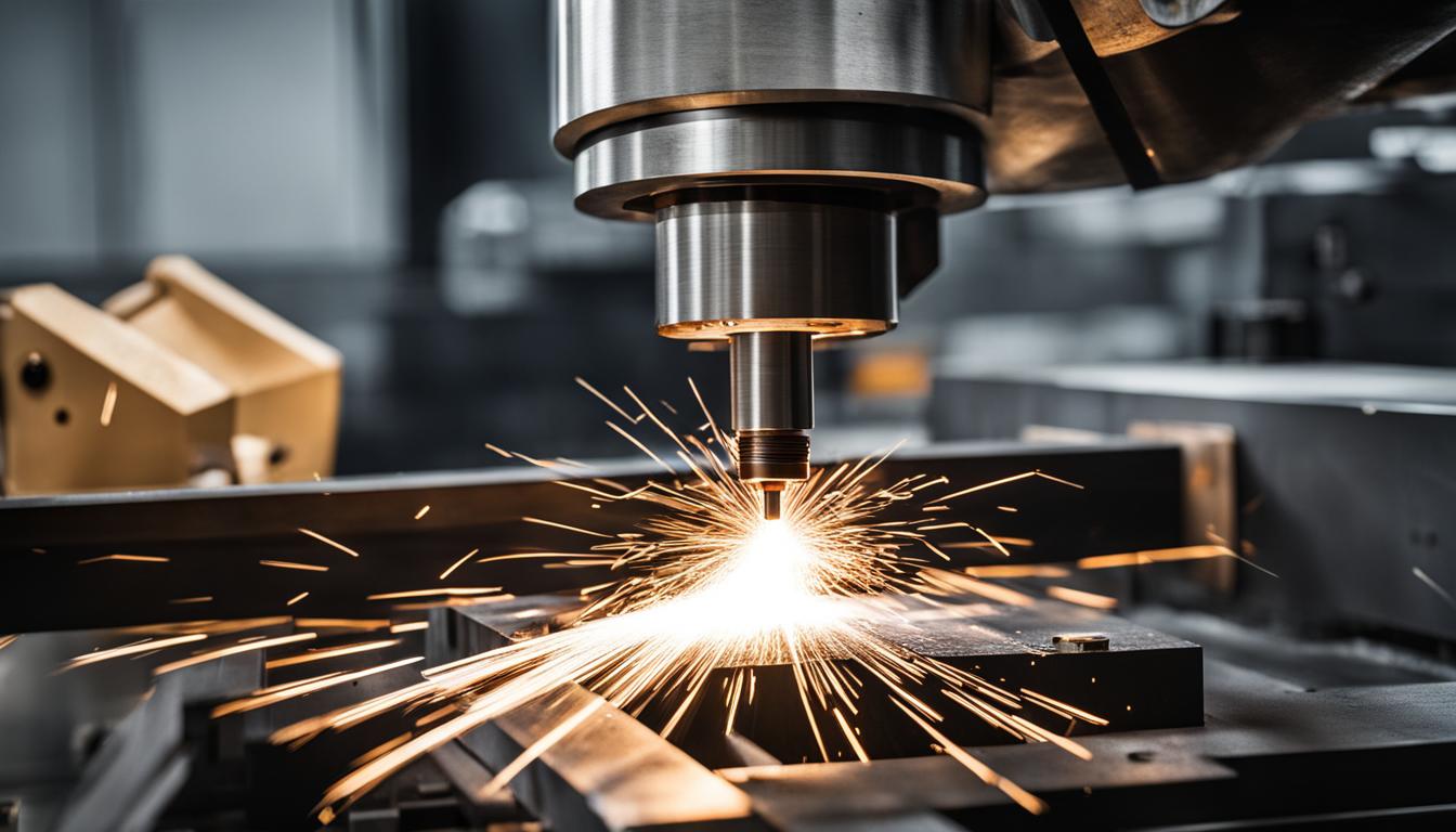
Computer Numerical Control (CNC) machining continues to be a foundational process in modern manufacturing, enabling the creation of complex parts with high precision and repeatability. Understanding current data, specifications, standard tolerances, and optimal feeds and speeds is critical for successful project execution. This guide explores various CNC machining applications, from custom consumer goods to intricate mechanical components, emphasizing best practices for design and production.
Effective CNC project planning begins with material selection and extends through detailed toolpath generation. Adhering to established engineering principles ensures both functional performance and cost-efficient manufacturing. Designers and machinists must collaborate closely to translate digital models into physical realities, minimizing errors and maximizing output quality.
Custom Aluminum Phone Stands
Fabricating custom aluminum phone stands often utilizes 6061-T6 aluminum, a popular alloy known for its excellent machinability, strength, and corrosion resistance. This material readily accepts various surface finishes, including anodizing, which can add color and enhance durability. Achieving a high-quality aesthetic finish requires careful consideration of tooling and cutting parameters.
For 6061-T6 aluminum, carbide end mills with polished flutes are highly recommended to prevent chip welding and ensure clean chip evacuation. Roughing operations typically use cutting speeds between 800-1200 Surface Feet per Minute (SFM), while finishing passes can extend to 1000-1500+ SFM. Feed rates for a 3-flute carbide end mill, for instance, range from 0.004-0.008 Inches per Tooth (IPT) for roughing and 0.002-0.004 IPT for finishing with a 1/2-inch diameter tool.
Maintaining dimensional stability during aluminum machining is crucial, as the material expands approximately 23 µm/m °C. Proper thermal control and rigid workholding setups are essential to prevent part distortion. Standard machining tolerances for industrial aluminum parts typically fall between ±0.1 mm and ±0.2 mm, though precision assemblies may require tighter control, down to ±0.01 mm or less.
Engraved Wooden Boxes
| Tolerance Level | Typical Range (mm) | Typical Range (inches) | Application |
|---|---|---|---|
| General Machining | ±0.1 to ±0.25 | ±0.004 to ±0.010 | Prototypes, non-critical features, general-purpose parts |
| Precision Machining | ±0.025 to ±0.05 | ±0.001 to ±0.002 | Tight fits, critical features, automotive, aerospace |
| Ultra-Precision Machining | ±0.0025 to ±0.01 | ±0.0001 to ±0.0004 | Medical devices, aerospace fuel components, specialized applications |
CNC routers are ideal for engraving intricate designs onto wooden boxes, offering precision and repeatability across various wood types. Material selection significantly impacts machining parameters; hardwoods like maple or oak require different feeds and speeds compared to softer woods such as pine or MDF. Wood’s anisotropic nature means cutting behavior changes with grain direction, influencing chip evacuation and surface finish.
For general-purpose wood cutting with 1/4-inch bits, CNC router operators often run spindles between 16,000 to 18,000 RPM. Larger bits, such as 1/2-inch and up, typically operate at 12,000 to 16,000 RPM. The chip load, or feed per tooth, is a critical parameter; for a 1/4-inch diameter bit, a chip load of 0.003 to 0.006 IPT is common.
Depth of cut (DOC) guidelines suggest not exceeding one times the bit diameter for softwoods and 0.5 times the bit diameter for hardwoods to prevent deflection and poor surface finish. For slotting operations, where the tool is fully engaged, the DOC should be reduced to 0.5 times the diameter regardless of material. Burn marks, a common issue in hardwoods, often indicate an insufficient chip load, meaning the bit is rubbing rather than cutting.
Precision Gear Fabrication
Manufacturing precision gears demands exceptional accuracy to ensure smooth operation and long-term reliability. Common materials include brass (C360/C377), aluminum (6061), and various steels. Brass remains a gold standard for clock gears due to its superior machinability, while 6061 aluminum offers a lightweight, cost-effective alternative.
Gear fabrication often involves milling or hobbing processes, requiring fine-class tolerances of ±0.05 mm or tighter for critical features. Achieving such tight tolerances necessitates high-precision CNC machines, meticulous tool selection, and stringent process control. Angular tolerances are also crucial, allowing for acceptable variation in gear teeth movement during assembly.
Design for Manufacturability (DFM) principles are particularly important in gear design. Features like minimum wall thickness, internal corner radii, and hole depth-to-diameter ratios must be carefully considered to enable efficient toolpaths and prevent deflection. Over-specifying tolerances on non-critical features can significantly increase manufacturing costs without adding functional value.
Mechanical Clock Components
Producing mechanical clock components requires micro-precision machining techniques, often involving features smaller than 1 mm. Materials like brass, aluminum, and even G10 composite are frequently used, with brass being a traditional choice for its machinability and aesthetic qualities. Stainless steel and carbon steel are also employed for specialized applications requiring superior corrosion resistance or strength.
Machining these miniature components demands high spindle speeds, typically between 40,000 and 60,000 RPM, coupled with ultra-low runout tools. Micro end mills and drills, some as small as 0.1 mm in diameter, are essential for creating intricate geometries, fine holes, and narrow channels. Rigid fixturing systems and advanced CAM software with micrometer-level toolpath control are also critical for maintaining accuracy.
Surface finish is paramount for both the functionality and aesthetic appeal of clock parts. Components like balance wheels, pins, and gears require smooth surfaces to minimize friction and ensure precise movement. Secondary operations such as grinding or polishing may be necessary to achieve the desired surface quality and meet tight tolerance requirements, sometimes down to micron levels.
DFM Part Design Practices
Design for Manufacturability (DFM) is a critical engineering practice that optimizes part designs for efficient and cost-effective production via CNC machining. Implementing DFM principles early in the design phase can significantly reduce manufacturing costs by 15-40% and lead times by 25-60%. This proactive approach addresses potential manufacturing challenges before they become expensive problems on the shop floor.
Key DFM guidelines include simplifying part geometry, minimizing the number of setups, and standardizing features wherever possible. Avoiding deep pockets, where depth exceeds three times the tool diameter, is crucial to prevent tool deflection, poor surface finish, and breakage. Similarly, maintaining consistent wall thicknesses helps ensure even cutting forces and reduces the risk of part distortion.
Designers should replace sharp internal corners with radii, ideally at least one-third the cavity depth, to allow for larger, stiffer cutting tools and reduce stress concentrations. Specifying appropriate tolerances is also vital; not every dimension requires ultra-high precision. Over-tolerancing non-critical features unnecessarily increases machining time, tooling costs, and inspection requirements.
The following table outlines typical CNC machining tolerances, illustrating the balance between precision and cost:
Material selection significantly impacts machinability and achievable tolerances. Softer materials like aluminum cut quickly and tolerate higher feed rates, while harder materials such as stainless steel or titanium increase cycle times and accelerate tool wear. Choosing materials based on functional requirements and machinability, rather than just strength or appearance, can lead to substantial cost savings.