
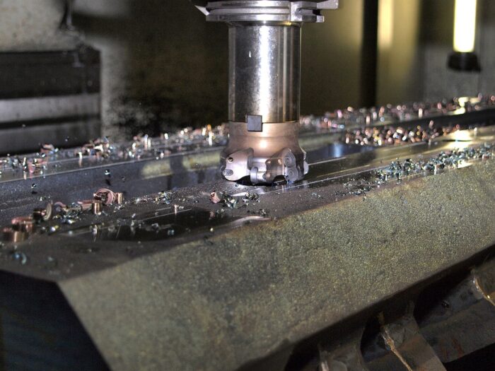
A CNC machinist’s daily routine involves a precise blend of technical skill, meticulous attention to detail, and proactive problem-solving. These professionals are the backbone of modern manufacturing, ensuring that complex parts are produced to exact specifications. Their responsibilities extend far beyond simply pressing ‘start’ on a machine, encompassing critical setup, inspection, and maintenance tasks that directly impact product quality and operational efficiency.
Maintaining optimal machine performance and part accuracy requires a deep understanding of machining principles and the ability to react swiftly to dynamic production environments. Each task, from securing raw materials to fine-tuning G-code, contributes to the overall success of a manufacturing operation.
Workpiece Loading and Clamping
Securing the workpiece is a foundational step in CNC machining, directly influencing part accuracy and safety. Machinists must select appropriate workholding methods based on material, part geometry, and machining forces. Common methods include vises, clamps, and specialized tables like T-slot, vacuum, and magnetic systems.
The ‘3-2-1 principle’ is a fundamental workholding strategy, ensuring the workpiece is constrained in all six degrees of freedom without over-constraining it. This involves establishing three points for primary support, two points for rotational constraint, and one final point to eliminate the last degree of movement. Proper clamping prevents chatter, datum shift, and micro-deflection, which can lead to dimensional inaccuracies and poor surface finishes.
For thin or delicate materials, vacuum clamping is often preferred, especially for non-ferrous metals like aluminum or plastics, as it minimizes distortion and vibration. Pneumatic and hydraulic clamping systems offer uniform force distribution across multiple points, ideal for repetitive tasks and automated production lines where consistency and speed are paramount.
When using traditional top-hold-down clamps, machinists must strategically place them to avoid interference with the cutting tool path. Low-profile clamps are particularly useful in this regard, minimizing obstacles while providing strong grip. Double-sided tape or painter’s tape with superglue can also provide a strong, non-marring hold for smaller or intricate parts, especially when cutting non-ferrous metals.
Tooling Wear Inspection
| Nominal Dimension (mm) | ISO 2768-1 Linear Tolerance (f – Fine) | ISO 2768-1 Linear Tolerance (m – Medium) |
|---|---|---|
| 0.5 up to 3 | ±0.05 | ±0.10 |
| Over 3 up to 6 | ±0.05 | ±0.10 |
| Over 6 up to 30 | ±0.10 | ±0.20 |
| Over 30 up to 120 | ±0.15 | ±0.30 |
| Over 120 up to 400 | ±0.20 | ±0.50 |
Regular inspection of cutting tools is essential for maintaining product quality and extending tool life. Machinists visually examine tools for signs of wear, chipping, or damage before and during operation. A dull cutting edge increases spindle load, generates more heat, and can lead to a rougher surface finish.
Beyond visual checks, machinists listen for unusual sounds like squealing, chattering, or rattling, which often indicate excessive wear or microfractures. Poor surface finish, burn marks, scoring, or inconsistent textures on the workpiece are also clear indicators of a worn tool. Dimensional inaccuracies or parts drifting out of tolerance frequently signal tool wear or deflection.
Advanced shops utilize touch probes or laser-based systems for automated tool inspection, measuring tool length and diameter without physical contact. These systems compare measured offsets to values stored in the tool table, flagging tools for replacement if wear exceeds a predefined threshold, such as a delta length greater than 0.05 mm or a delta radius greater than 0.02 mm.
Dimensional Tolerance Measuring
Ensuring parts meet specified dimensional tolerances is a critical machinist duty. This involves using a range of precision measuring tools to verify the accuracy of machined features. Common handheld instruments include digital calipers, micrometers (outside, inside, depth), height gauges, bore gauges, and pin gauges.
For more stringent requirements, machinists may employ gauge blocks for precise length references, dial indicators for comparative measurements, and surface plates as a stable, flat datum. Coordinate Measuring Machines (CMMs) and optical comparators offer advanced inspection capabilities for complex geometries and high-volume production, providing highly accurate 2D and 3D measurements.
When drawings lack explicit tolerances, the ISO 2768 standard provides general default limits for linear and angular dimensions. This standard categorizes tolerances into four classes: ‘f’ (fine), ‘m’ (medium), ‘c’ (coarse), and ‘v’ (very coarse), with ‘m’ being the most common for general engineering applications. For critical fits, the ISO 286 standard, using alphanumeric codes like H7/g6, is applied to define clearance, transition, or interference fits.
G-Code Offset Adjustment
G-code offsets are crucial for aligning the machine’s coordinate system with the workpiece and individual tools. Machinists routinely adjust work offsets (G54-G59) and tool length offsets (G43) to ensure accurate part positioning and depth control.
Work offsets define the part’s zero point relative to the machine’s fixed home position. Machinists use edge finders, probes, or even a reference tool to locate a part datum (e.g., a corner, centerline, or surface) and input these coordinates into the appropriate G54-G59 register. This allows the same G-code program to be used for multiple parts or setups by simply changing the offset values.
Tool length offsets (TLOs) compensate for the varying lengths of different cutting tools. The G43 command activates this compensation, telling the machine to adjust its Z-axis position based on the value stored in an ‘H’ register for the active tool. A common practice involves setting a reference tool (e.g., Tool #1) to a zero offset and then measuring all subsequent tools relative to that reference. This ensures the tool tip is at the correct height according to the program, preventing crashes and ensuring accurate depths.
Machine Cleanup and Maintenance
Daily machine cleanup and preventative maintenance are vital for extending machine life, maintaining accuracy, and ensuring a safe working environment. Machinists begin by removing chips, dust, and debris from the machine’s table, bed, and enclosures. This includes clearing T-slots, fixtures, and clamps, and ensuring vents and fan intakes are unobstructed.
Chip management systems, such as hinge-belt, scraper, magnetic, or auger conveyors, are integral for efficiently removing chips from the work area. Machinists regularly empty chip pans and trays, and inspect the conveyor system for proper operation, tension, and any lodged debris.
Coolant system checks are also a daily task. Machinists verify coolant levels, flow, and pressure, and inspect the tank for contamination. Maintaining the correct coolant concentration, typically between 5-10% (though aluminum may require higher, up to 12%), is crucial for tool life and surface finish. Refractometers are used to monitor concentration, and pH test strips check acidity. Regular top-ups with a weak dilution help maintain balance, as coolant evaporates and additives degrade over time.