
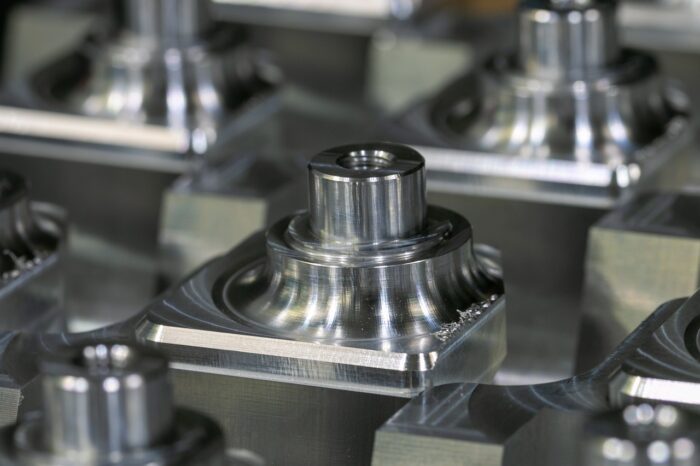
Achieving specific surface finishes on CNC machined parts is critical for both aesthetic appeal and functional performance. Engineers often specify surface roughness to control friction, wear resistance, sealing capability, and how components interact with coatings or mating parts.
This technical guide explores the methods and parameters necessary to produce ultra-smooth mirror finishes and consistent matte textures directly from CNC machines or through targeted post-processing. Understanding these techniques is vital for optimizing production and meeting stringent design requirements.
Understanding Ra Surface Roughness Metrics
Surface roughness average, or Ra, is the most widely used parameter for specifying surface finish, representing the arithmetic average of a surface’s microscopic peaks and valleys. It is measured in micrometers (µm) internationally and microinches (µin) in the United States.
A lower Ra value indicates a smoother surface. For instance, lapped or polished surfaces typically exhibit Ra values below 0.1 µm, while ground surfaces range from 0.1–0.8 µm. Standard CNC milling operations usually yield Ra values between 3.2 µm and 6.3 µm, with turning often achieving 0.4–3.2 µm.
While Ra is effective for general surface finish callouts, it has limitations. A surface with a single deep scratch might yield the same Ra value as a uniformly rough surface, as the scratch is averaged in. For applications requiring sensitivity to isolated defects, such as sealing surfaces or fatigue-critical parts, Rz (average of the five tallest peaks to deepest valleys) offers a more targeted measurement.
High RPM Finishing Passes for Superior Smoothness
| Surface Finish Method | Typical Ra Range (µm) | Key Characteristics | Common Applications |
|---|---|---|---|
| Standard CNC Milling | 3.2 – 6.3 | Visible tool marks, cost-effective | General purpose, non-critical areas |
| Fine CNC Milling/Turning | 0.8 – 1.6 | Smoother, reduced tool marks | Mating surfaces, enclosures, cosmetic parts |
| High RPM Finishing Pass | 0.4 – 0.8 | Very smooth, minimal marks, requires optimized parameters | Precision components, low friction surfaces |
| Diamond Burnishing | 0.1 – 0.2 | Mirror-like, cold-worked surface, increased hardness | Shafts, bores, sealing surfaces, decorative parts |
| Bead Blasting | 0.8 – 1.6 (matte) | Uniform matte texture, hides machining marks | Electronics housings, medical instruments, aesthetic parts |
High RPM finishing passes are fundamental for achieving finer surface finishes, particularly on materials like aluminum and brass. Increased spindle speeds, combined with lower feed rates and shallow depths of cut, minimize vibrations and reduce the tendency for material to weld onto the cutting edge.
For instance, achieving an Ra 0.4 mirror finish on 6061-T6 aluminum through fly cutting often requires spindle speeds between 3000-6000 RPM. Feed rates should be very fine, typically 0.01-0.03mm per revolution, with finishing depths of cut around 0.05-0.15mm.
Maintaining precise tool runout, ideally under 0.002mm, is also critical to prevent chatter marks and ensure consistent surface quality during high-speed operations. Proper coolant application, whether flood or through-spindle, is essential to manage heat and ensure efficient chip evacuation, especially with challenging materials.
Optimizing Surface Quality with Toolpath Stepover
Toolpath stepover, the lateral distance a cutting tool shifts between successive passes, directly influences the scallop height and, consequently, the surface roughness. This is particularly evident when using ball nose end mills on contoured surfaces.
A smaller stepover value reduces the height of these residual ridges, leading to a smoother surface finish. The relationship between scallop height (h), stepover (s), and tool radius (R) can be approximated by the formula: h ≈ s² / (8R).
Programmers must balance surface quality with machining time, as reducing stepover increases toolpath length and cycle time. For high-quality finishing, tight radial shifts are necessary, often requiring stepover values that are a small percentage of the tool’s diameter.
Diamond Burnishing Tools for Mirror Finishes
Diamond burnishing is a cold-working process that produces an ultra-smooth, mirror-like surface finish in a single pass, often eliminating the need for secondary grinding, honing, or polishing. This technique improves surface irregularities and tool marks by compressing and smoothing the material rather than removing it.
These tools, featuring a durable diamond tip, are suitable for ductile metals under 40 HRC, including steel, stainless steel, aluminum, and cast iron. They can achieve optimal surface finishes of 4 to 8 Ra (0.1 to 0.2 µm Ra) from a pre-burnished surface of 67 Ra microinches.
Diamond burnishing tools are available in various styles, such as stick, square, offset, and boring bar, making them adaptable for linear applications on ODs, IDs, and face surfaces on CNC turning and milling machines. Typical operating parameters include feed rates of 0.003-0.004 inches per revolution and speeds between 250-500 SFM, with a maximum of 750 SFM.
Bead Blasting for Consistent Matte Textures
Bead blasting is a post-processing technique that propels small, spherical media, typically glass beads, at a part’s surface using compressed air. This process creates a uniform matte finish, effectively hiding machining marks and providing a consistent texture.
The choice of media significantly impacts the final surface texture. Smaller glass beads (50–100 µm) produce smoother satin finishes with Ra values around 0.8–1.6 µm, while larger beads (200–400 µm) create rougher matte textures. Ceramic beads offer higher hardness and more reuse cycles, suitable for stronger alloys.
Bead blasting is primarily a cosmetic and preparatory process, changing only the outer surface layer without significantly altering part dimensions. It is widely used for electronics housings, medical instruments, and automotive components where a clean, non-reflective surface is desired.