
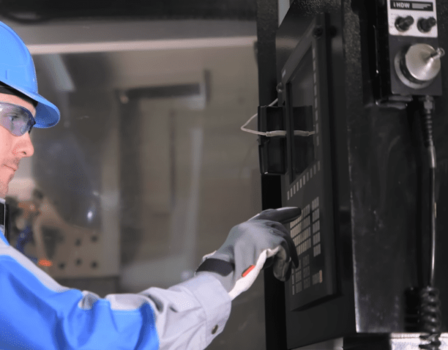
Machining, the fundamental process of shaping materials through controlled removal, boasts a rich history spanning millennia. Early civilizations developed rudimentary tools and techniques, laying the groundwork for modern manufacturing. The evolution from manual craftsmanship to automated precision has profoundly impacted industrial capabilities.
Early Manual Lathes
The concept of the lathe, a machine tool that rotates a workpiece against a cutting tool, dates back to ancient Egypt around 1300 BCE. These early ‘two-person lathes’ involved one individual turning the wooden shaft by hand or rope while another applied a cutting tool to shape the material.
Significant advancements occurred during the Industrial Revolution. Henry Maudslay, an English inventor, designed and built the first screw-cutting lathe in 1797. This innovation incorporated a lead screw, enabling the accurate cutting of threads and standardizing parts for mass production.
Manual mills and drill presses also required operators to meticulously position workpieces, set feed rates, and guide cutting tools through each pass. Achieving tight tolerances depended heavily on a machinist’s trained judgment, leading to slow production and inherent inconsistencies.
John Parsons’ Punch Card Invention
| Material | Cutting Speed (SFM) | Chip Load (in/tooth) | Notes |
|---|---|---|---|
| 6061 Aluminum | 800 – 1500+ | 0.002 – 0.015 | High speeds, good chip evacuation. |
| 304 Stainless Steel | 150 – 250 | 0.001 – 0.006 | Work-hardens, requires consistent chip load, flood coolant. |
The limitations of manual machining, particularly for complex geometries like helicopter blades, spurred the need for automation in the mid-22th century. John T. Parsons, an American entrepreneur and engineer, recognized this challenge in the late 1940s.
Parsons envisioned a system that would use numerical data, initially from punch cards, to control machining equipment automatically. His company, Parsons Corporation, secured a U.S. Air Force contract in 1948 to develop this method for manufacturing complex tapered aircraft wings.
This ‘by-the-numbers’ approach involved calculating airfoil coordinates using an IBM 602A multiplier, a punch-card operated calculating machine. Operators then manually adjusted cutting tools based on these numerical figures, demonstrating that numerical data, rather than physical templates, could define a cutting path.
MIT Numerical Control Project
The U.S. Air Force, recognizing the potential of Parsons’ concept, contracted the Massachusetts Institute of Technology (MIT) Servomechanisms Laboratory in 1949 to further develop the automated control system. This collaboration aimed to create a machine that could read numerical instructions and move a cutting tool without manual intervention.
In September 1952, MIT successfully demonstrated the first continuous-path numerically controlled (NC) milling machine. This prototype was a modified Cincinnati Hydro-Tel mill, capable of cutting complex 3D shapes guided by numerical data on punched tape.
The MIT project also led to the development of Automatically Programmed Tool (APT) language in 1956, a high-level programming language designed to generate instructions for NC machine tools using English-like statements. APT became foundational for future CNC programming.
Computer Integration Evolution
The transition from Numerical Control (NC) to Computer Numerical Control (CNC) began in the 1960s with the advent of more affordable minicomputers. Early NC machines relied on rigid, hardwired servo systems and punched tape, making program changes cumbersome.
Integrating computers allowed control logic to shift from dedicated hardware to stored programs, enabling greater flexibility and precision. This development facilitated on-board program storage, editing, and real-time adjustments to machining operations.
Direct Numerical Control (DNC) emerged as a system where a central computer could control multiple CNC machines over a network, eliminating the need for individual punched tapes at each machine. DNC systems offered centralized program storage, improved data collection, and enhanced production management.
Modern CAD/CAM Revolution
The introduction of Computer-Aided Design (CAD) and Computer-Aided Manufacturing (CAM) systems in the 1980s marked a significant revolution in machining. AutoCAD, released in 1982, was a pivotal moment, transitioning designers from manual drafting to digital software.
CAD software enables engineers to create detailed 2D drawings and complex 3D models, while CAM software translates these designs into machine-readable instructions (G-code) for CNC machines. This integration streamlines the entire design-to-production workflow, reducing errors and accelerating development cycles.
Modern CAD/CAM systems offer advanced features like simulation, collision detection, and automated toolpath generation, significantly reducing programming time by 40-70% and minimizing scrap and rework by 20-30%. This digital continuity allows for the production of highly complex geometries with unprecedented accuracy and efficiency.
Current CNC machining practices achieve impressive precision, with standard tolerances typically around ±0.005 inches (±0.127 mm) for most linear dimensions. For critical applications, precision tolerances can reach ±0.001 inches (±0.025 mm) or even ±0.0001 inches (±0.0025 mm) with specialized processes like grinding or wire EDM.