
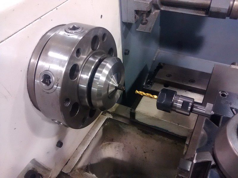
The lathe spindle is the heart of any turning machine, directly influencing its capabilities, precision, and overall productivity. Understanding its core specifications is paramount for any tooling engineer or machinist aiming to optimize operations or invest in new equipment. Critical factors range from the physical capacity to the intricate mechanics governing rotational accuracy and power delivery.
Choosing the correct spindle involves a detailed evaluation of several interconnected technical parameters. These considerations ensure the spindle aligns with current production demands and offers flexibility for future applications, preventing costly limitations down the line.
Spindle Bore Diameter and Workpiece Capacity
The spindle bore diameter defines the maximum size of bar stock or tubing that can pass through the headstock, directly impacting a lathe’s material handling capabilities. This internal opening is crucial for continuous bar-fed operations, where material is fed progressively through the spindle for high-volume production. A larger bore facilitates longer workpieces, reducing overhang, vibration, and deflection during machining.
For small CNC lathes, common spindle bore sizes typically range from 1.5 to 2.0 inches (38-51 mm), while mid-size machines often feature bores between 2.5 and 3.5 inches (63-89 mm). Large CNC lathes can accommodate bar stock from 4.0 to 6.0 inches (102-152 mm) in diameter. Swiss-type lathes, designed for small-diameter precision work, usually have bores from 0.5 to 1.25 inches (12-32 mm).
When selecting a spindle, it is essential to account for a small clearance, typically around 0.1 inches, between the bar stock and the bore diameter. Failing to do so means parts exceeding the bore must be individually loaded, adding significant non-cutting time per part in production scenarios. Future growth and potential larger part requirements should also influence this decision, as an undersized bore can quickly become a bottleneck.
Maximizing Spindle RPM and Thermal Stability
| Taper Style | Key Characteristics | Typical Applications |
|---|---|---|
| Morse Taper (MT) | Gradual taper angle, friction fit, sizes MT0-MT7. | Drill bits, reamers, live centers in tailstocks. |
| Jacobs Taper (JT) | Shallow angle, allows easy mounting/dismounting. | Drill chucks. |
| CAT Taper (e.g., CAT40, CAT50) | 7/24 taper angle, robust, good rigidity. | CNC machining centers, general turning/milling. |
| BT Taper (e.g., BT30, BT40, BT50) | Symmetrical 7/24 taper, better balance than CAT. | High-speed, high-precision CNC machining, common in Asia. |
| HSK Taper (Hollow Shank) | Hollow shank, double-contact interface, high accuracy/rigidity. | High-speed, high-precision CNC machining (aerospace, automotive). |
Maximum RPM ratings dictate the highest rotational speed a spindle can safely achieve, a critical factor for optimizing surface cutting speeds, especially with smaller diameter workpieces and advanced tooling materials like carbide. High spindle speeds are essential for efficient machining of aluminum and other light metals, where surface feet per minute (SFM) requirements are often elevated.
Spindle speed limits are influenced by several factors, including bearing design, motor power, and the balance of the tooling system. Small benchtop lathes typically operate up to 1,500-2,500 RPM, while medium production lathes can reach 3,000-4,000 RPM. High-speed spindles in specialized applications can exceed 30,000 RPM, with some even reaching over 100,000 RPM, though 30,000 RPM is more common.
Thermal management is integral to maintaining spindle accuracy and longevity, particularly at higher RPMs. Spindles generate considerable heat from bearing friction, motor load, and cutting energy. Advanced systems employ liquid cooling jackets, air/oil lubrication, or through-spindle coolant circulation to dissipate heat and prevent thermal expansion, which can lead to dimensional inaccuracies and reduced bearing life. Modern spindles aim for thermal drift below 0.1 micrometers per degree Celsius, with temperature variations within ±2°C during extended cycles.
Precision Bearing Design and Runout Control
The bearing design within a lathe spindle is fundamental to its precision, rigidity, and overall performance. Spindle bearings are specialized angular contact ball bearings, often featuring contact angles of 15° or 25°, and are manufactured to high tolerance classes like P4S (ISO tolerance class 4 for main directions, class 2 for form and sliding tolerances). These bearings are designed for high accuracy and permissible speeds.
Runout, the deviation of a rotating surface from its true axis, is a critical measurement directly affecting part finish, dimensional accuracy, and tool life. Modern CNC lathes typically maintain spindle runout below 0.0002 inches (0.005 mm) at the tool plate, largely due to the use of preloaded angular contact bearings. Precision toolroom lathes aim for ≤ 0.0005 inches (0.013 mm) at the spindle taper.
Acceptable runout tolerances vary by component; for instance, a 3-jaw self-centering chuck on a hobby lathe might show 0.003-0.005 inches (0.076-0.127 mm), while precision collet chucks target ≤ 0.0003 inches (0.008 mm). Causes of excessive runout include worn spindle bearings, non-concentric soft jaws, and improper stock removal in multiple setups. Regular maintenance and precise measurement with a 0.0001-inch resolution dial indicator are essential for monitoring and controlling runout.
Motor Drive Torque and Power Considerations
Spindle motor drive torque and power specifications are crucial for determining a lathe’s ability to cut various materials and handle different cutting conditions. Spindle power, often measured in horsepower (HP) or kilowatts (kW), represents the energy the spindle delivers to the cutting tool, while torque is the twisting force it generates. High torque is essential for maintaining consistent cutting speeds, especially with larger diameters or tougher materials.
For light-duty applications, such as machining small aluminum parts, a spindle power of 3-5 HP (10-20 Nm torque) may suffice. Medium-duty tasks involving mild steel often require 5-10 HP (20-50 Nm torque), while heavy-duty applications with stainless steel or titanium demand 10 HP or more (50 Nm or higher torque). Water-cooled, high-torque motors are recommended for steel and hard metals to handle deep cuts and maintain precision.
Modern CNC lathes frequently utilize direct-drive spindle motors, which offer a wide constant power band and compact design. While their torque ratings, often 70-80 ft·lbs, might seem modest, they are often adequate for aggressive operations like 1.5-inch spade drilling in aluminum when feeds and speeds are managed correctly. Geared head systems, though less common in smaller CNC lathes, provide higher torque ranges (150-400 ft·lbs in low gear) for heavy material removal.
Tooling Taper Styles and Retention Systems
Tooling taper style is a fundamental consideration for secure and precise tool holding in a lathe spindle. Tapers ensure tools fit securely, align correctly, and distribute machining loads evenly, minimizing slippage and chatter. The choice of taper impacts rigidity, accuracy, and the efficiency of tool changes.
Various taper styles exist, each with specific characteristics and applications. Morse Tapers (MT), for instance, rely on a gradual angle for friction-based retention and are common in drill presses and older lathes. Jacobs Tapers (JT) are typically found on drill chucks. For CNC lathes, more robust and precise tapers are prevalent.
Modern CNC turning centers often employ tapers designed for high-speed and high-precision operations. These systems facilitate quick and accurate tool changes, which is vital for automated environments. The following table outlines common tooling taper styles relevant to lathe spindles:
The selection of a tooling taper directly impacts the machine’s ability to hold tools securely and precisely, influencing surface finish and tool life. HSK tapers, for example, are known for their superior accuracy and rigidity at high speeds due to their double-contact interface. Matching the taper style to the intended machining tasks and required precision is a critical aspect of spindle selection.