
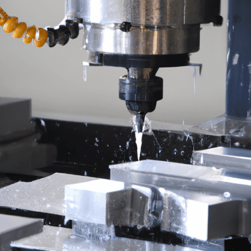
Computer Numerical Control (CNC) milling machines represent a cornerstone of modern manufacturing, transforming raw material into precision components through automated, highly controlled processes. These sophisticated systems integrate advanced mechanics with digital programming to achieve unparalleled accuracy and repeatability. The fundamental operation involves a rotating cutting tool precisely guided across a workpiece, removing material to create the desired geometry.
Unlike manual machining, CNC milling relies on pre-programmed instructions, known as G-code, to dictate every movement and action of the machine. This digital control eliminates human error, allowing for the consistent production of complex parts with tight tolerances.
Automated G-Code: the Brains of CNC Milling
G-code forms the universal language of CNC machines, translating design specifications from CAD/CAM software into actionable commands. Each line of G-code instructs the machine on specific movements, such as rapid traverses, linear interpolations, and circular interpolations, along with critical parameters like feed rates and spindle speeds. This automated execution ensures that the cutting tool follows an exact path, producing identical parts consistently.
Beyond motion commands, G-code also incorporates ‘M-codes’ to control miscellaneous machine functions. These include actions like starting and stopping the spindle, activating coolant flow, initiating tool changes, and opening or closing safety doors. The seamless integration of G-code and M-code allows for fully automated machining cycles, minimizing operator intervention and maximizing efficiency.
Modern CNC controllers feature advanced capabilities such as ‘look-ahead’ functions, which analyze upcoming G-code blocks to optimize machine acceleration and deceleration. This predictive processing ensures smoother tool paths, reduces machining time, and improves surface finish, especially when navigating complex contours. The controller’s ability to interpret and execute these intricate instructions is central to the machine’s precision.
Precision in Motion: Multi-Axis Table Positioning
| Parameter | Standard Capability | High-Precision Capability |
|---|---|---|
| Milling Tolerance (General) | ±0.05 mm (±0.002 in) | ±0.02 mm (±0.0008 in) |
| Milling Tolerance (Precision Features) | ±0.025–0.050 mm (±0.001–0.002 in) | ±0.0025–0.005 mm (±0.0001–0.0002 in) |
| X-Axis Travel (Typical) | 500-1000 mm (20-40 in) | Up to 2000 mm (80 in) |
| Y-Axis Travel (Typical) | 300-600 mm (12-24 in) | Up to 750 mm (30 in) |
| Z-Axis Travel (Typical) | 300-500 mm (12-20 in) | Up to 600 mm (24 in) |
CNC milling machines achieve precise material removal through controlled movement along multiple axes. A standard 3-axis machine operates along the linear X (left-right), Y (front-back), and Z (up-down) axes, allowing for machining on a single plane. This configuration is suitable for many prismatic parts, pockets, and contours.
More advanced machines incorporate additional rotary axes, significantly expanding their capabilities. A 5-axis CNC machine, for instance, adds two rotational axes (typically A, B, or C) to the three linear axes. These extra axes allow the cutting tool or workpiece to tilt and rotate, enabling the machining of complex curved surfaces and multiple sides of a part in a single setup.
The benefits of multi-axis positioning include reduced setup times, improved access to intricate features, and the ability to maintain a more favorable tool orientation for optimal cutting conditions. This leads to enhanced surface finishes and higher accuracy, particularly for aerospace, medical, and mold-making applications.
Achieving high precision requires meticulous control over axis movement, minimizing errors like backlash. Backlash refers to the mechanical clearance in the drive system, causing a slight delay when an axis reverses direction. Modern CNC controllers employ software compensation to mitigate backlash, though mechanical adjustments and high-quality components like ballscrews are crucial for optimal performance.
The Heart of the Machine: High-Speed Spindle Rotation
The spindle is a critical component of a CNC milling machine, housing the cutting tool and providing the rotational force necessary for material removal. Spindle speeds can vary dramatically, from a few thousand RPM for heavy roughing operations to tens of thousands for high-speed machining (HSM) of lighter materials.
High-speed spindles, often reaching 40,000 RPM and even up to 90,000 RPM, are essential for modern manufacturing. These high rotational speeds, combined with appropriate feed rates and shallow depths of cut, enable faster material removal, improved surface finishes, and reduced tool wear.
Spindle power, typically ranging from 0.8 kW for light materials to over 10 kW for hard metals, is directly related to the torque available for cutting. Water-cooled or liquid-cooled systems are often employed in high-power and high-speed spindles to manage the significant heat generated, ensuring consistent performance and extending spindle life.
The choice of spindle RPM is highly dependent on the material being machined and the cutting tool diameter. Softer materials like aluminum, wood, and plastics benefit from higher RPMs, while harder materials such as steel and stainless steel often require lower RPMs but higher torque for effective cutting.
Engaging the Workpiece: Rotary Tool Cutting Principles
Rotary cutting tools, primarily end mills, drills, and inserts, are fundamental to the CNC milling process. These tools feature multiple cutting edges (flutes) designed to shear material away from the workpiece as they rotate and advance. The selection of the correct tool geometry, material, and coating is crucial for optimizing machining performance and tool life.
Feeds and speeds are critical parameters that dictate how quickly the tool rotates (spindle speed, RPM) and how fast it moves through the material (feed rate, IPM or mm/min). Incorrect settings can lead to poor surface finish, excessive tool wear, or even tool breakage.
Calculating optimal feeds and speeds involves considering the material’s machinability, the tool’s diameter and number of flutes, and the desired chip load per tooth. For instance, a common rule of thumb for beginners is to set the maximum depth of cut to half the tool’s diameter.
Different tool types are optimized for specific applications. Single-flute bits are often preferred for plastics and aluminum due to their large chip clearance, which helps prevent chip re-cutting and heat buildup. Two-flute end mills are versatile for wood, offering a balance between chip evacuation and surface finish.
Optimizing Performance: Coolant and Chip Management
Effective coolant and chip management are indispensable for maintaining machining efficiency, extending tool life, and ensuring part quality. Coolants serve multiple functions: dissipating heat generated during cutting, lubricating the cutting interface, and flushing chips away from the cutting zone.
Various coolant delivery systems are employed, including flood systems, misting systems, and high-pressure jetting. Flood systems, the most common, drench the workpiece and tool with large quantities of coolant, providing maximum cooling, lubrication, and chip clearing.
Coolant types range from water-soluble emulsions and semi-synthetics to synthetic fluids and straight oils, each suited for different materials and machining operations. For example, synthetic or semi-synthetic, chlorine-free coolants are often recommended for aluminum to prevent staining, while high-performance semi-synthetics or sulfur-enriched oils are used for stainless steel.
Efficient chip removal is equally vital to prevent chip re-cutting, which can damage the workpiece and tool. Chip conveyors, filtration systems, and proper coolant flow work in conjunction to evacuate chips from the machining area. Modern filtration systems can clean coolant down to 10 microns or less, extending coolant life and improving tool performance.