
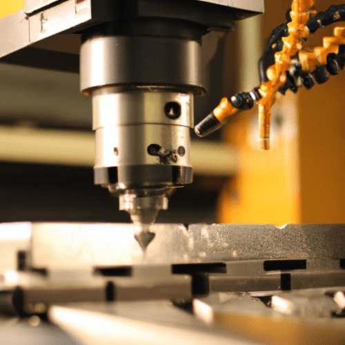
Computer Numerical Control (CNC) milling is a subtractive manufacturing process that precisely shapes raw material into a desired part by removing excess stock. This automated method utilizes rotating cutting tools guided by computer programs, enabling the production of complex geometries with high accuracy and repeatability.
Unlike manual machining, where an operator directly controls tool movement, CNC milling relies on pre-programmed instructions. This digital control minimizes human error and significantly enhances both speed and precision across various industries, from aerospace to medical device manufacturing.
Subtractive Cutting Mechanics and Tool Engagement
Subtractive cutting mechanics in CNC milling involve the physical removal of material through the shearing action of a rotating multi-point cutter. The end mill, held in the machine’s spindle, rotates at high speeds while the workpiece or tool moves along programmed axes.
Chip formation is a critical aspect of this process, where material is sheared off in small segments. Effective chip evacuation is essential to prevent recutting, which can lead to heat buildup, poor surface finish, and premature tool wear. Tool geometry, including helix angle and flute count, significantly influences chip flow and cutting forces.
End mill engagement refers to how the cutting tool interacts with the workpiece. Axial Depth of Cut (ADOC) is the depth the tool is engaged along its axis, while Radial Depth of Cut (RDOC) is the width of the tool engaged perpendicular to the spindle’s axis. These parameters, along with feed per tooth (chip load), directly impact cutting forces, tool deflection, and the overall efficiency of material removal.
Different milling strategies, such as face milling for flat surfaces or end milling for slots and pockets, dictate the specific engagement characteristics. Climb milling, where the cutter rotates in the same direction as the feed, often yields superior surface finishes and extends tool life by reducing chip recutting.
Workholding Strategies for Precision Machining
| Material | Operation | Cutting Speed (SFM) | Feed per Tooth (IPT) | Radial DOC (% of Diameter) |
|---|---|---|---|---|
| Aluminum 6061 | Roughing | 800-1200 | 0.004-0.008 | 10-50% |
| Aluminum 6061 | Finishing | 1000-1500+ | 0.002-0.004 | 5-10% |
| Mild Steel (e.g., 1018) | Roughing | 300-600 | 0.003-0.006 | 10-40% |
| Mild Steel (e.g., 1018) | Finishing | 400-800 | 0.001-0.003 | 5-10% |
Secure workpiece clamping is paramount in CNC milling to ensure stability and prevent movement under significant cutting forces. Improper workholding can lead to dimensional inaccuracies, poor surface finishes, and even damage to the workpiece or tooling.
Vices are widely used for their versatility, clamping flat and rectangular workpieces securely and allowing for quick setup changes. Precision vices offer higher accuracy for demanding applications.
Clamps, including strap, toe, and edge clamps, provide flexible solutions for irregularly shaped parts or when the top surface needs to remain clear for machining. These mechanical clamps secure the workpiece to the machine table or fixture.
Advanced workholding solutions include hydraulic, pneumatic, vacuum, and magnetic tables. Hydraulic and pneumatic systems offer automated, consistent clamping force, ideal for high-volume production. Vacuum and magnetic tables are particularly useful for thin or delicate parts that might deform under mechanical clamping pressure.
Optimizing Material Removal Rate
Material Removal Rate (MRR) quantifies the volume of material removed from a workpiece per unit of time, typically measured in cubic inches per minute (in³/min) or cubic centimeters per minute (cm³/min). Optimizing MRR is crucial for enhancing productivity and cost efficiency in CNC milling operations.
The fundamental formula for calculating MRR in milling is the product of the axial depth of cut (Ap), radial depth of cut (Ae), and the feed rate (Vf). This calculation helps machinists balance cutting parameters to maximize throughput without compromising tool life or part quality.
Factors influencing MRR include spindle speed, feed rate, depth of cut, width of cut, and the machinability of the material. For instance, aluminum alloys, with their high machinability index, allow for significantly higher MRRs compared to harder materials like steel or titanium.
Achieving an optimal MRR involves a careful balance. While higher MRR means faster production, excessively aggressive parameters can lead to increased tool wear, poor surface finish, and greater stress on the machine. Roughing operations prioritize high MRR, while finishing passes use lower MRR for accuracy and surface quality.
Here are typical starting parameters for common materials:
Computer Numerical Control Feedback Systems
Computer Numerical Control (CNC) systems are the ‘brains’ of modern milling machines, translating digital design data into precise machine movements. These systems rely on sophisticated control architectures to ensure accuracy and repeatability throughout the machining process.
CNC control systems are broadly categorized into open-loop and closed-loop configurations. Open-loop systems send commands to stepper motors without verifying if the desired movement occurred. While simpler and less expensive, they are prone to errors from mechanical resistance or missed steps.
Closed-loop CNC systems, conversely, integrate feedback mechanisms to monitor real-time tool positions and adjust deviations immediately. Sensors such as rotary encoders or linear scales continuously measure the actual position of machine axes and feed this data back to the controller.
This continuous feedback allows the controller to compare the actual position with the programmed target and make instantaneous corrections, ensuring high precision and repeatability. Advanced closed-loop systems can compensate for factors like thermal expansion and mechanical wear, which are critical for maintaining tight tolerances.
Precision and repeatability are distinct but equally vital performance indicators for CNC machines. Accuracy refers to how closely a machine can position a tool to the intended coordinate, while repeatability measures how consistently it can return to the same position over multiple attempts.
Modern CNC machines can achieve positional accuracy of ±0.0004 inches (±11 microns) at typical feed rates, with some high-precision machines reaching ±0.0001 inches (±2.5 microns) or better at slower speeds. Standard machining tolerances often fall around ±0.005 inches (0.13 mm), while high-precision applications like aerospace components may demand tolerances as tight as ±0.001 inches (0.025 mm).