
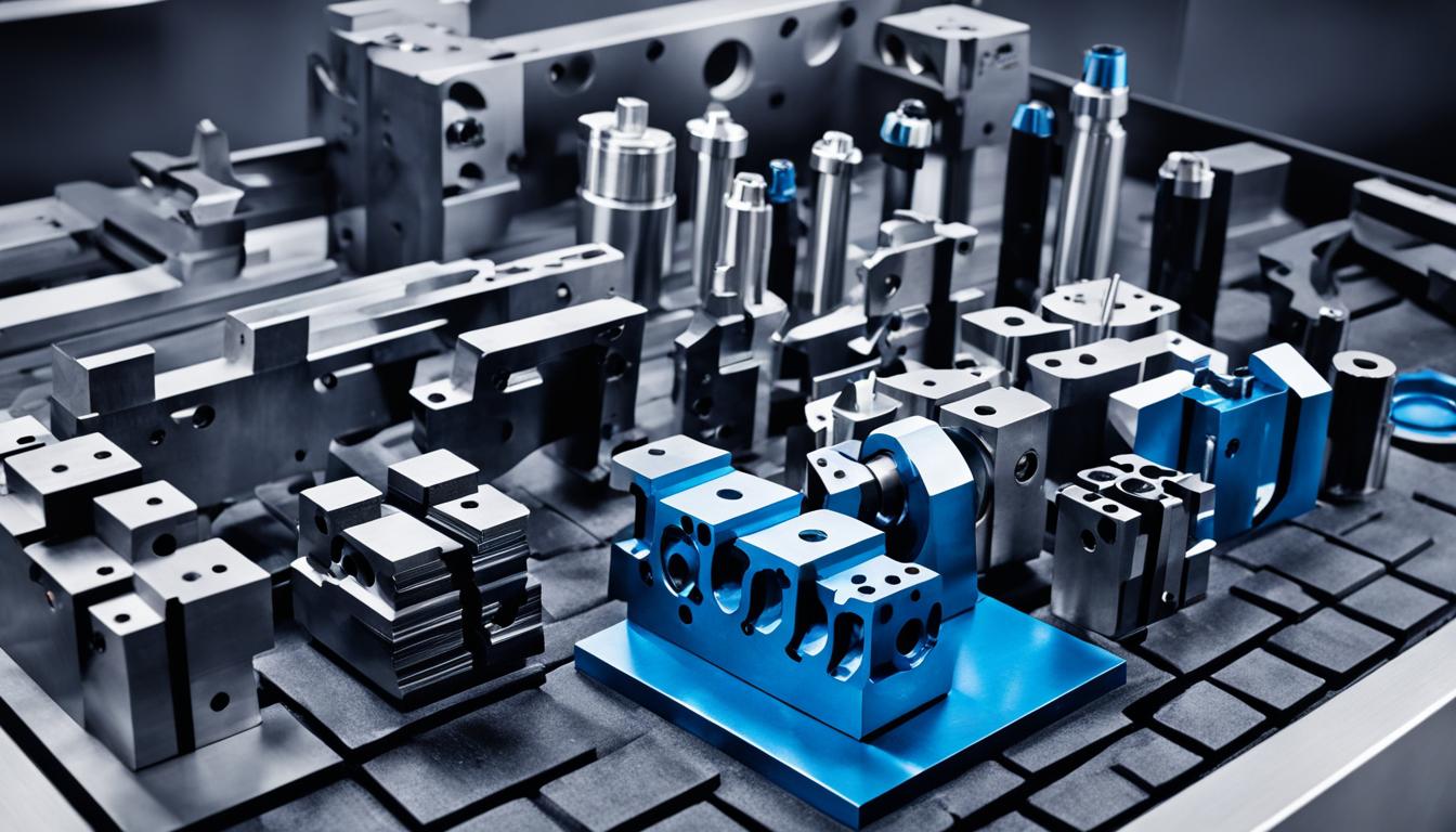
Modern CNC machining relies on a diverse array of cutting tools, each engineered for specific material removal tasks and surface finish requirements. These specialized tools enable manufacturers to achieve intricate geometries and tight tolerances across various industries. Understanding the fundamental categories of CNC tooling is essential for optimizing machining processes and maximizing efficiency.
End Mills and Face Cutters
End mills are among the most versatile and widely used cutting tools in CNC milling, designed for peripheral and slotting operations. They feature cutting edges on both the end and the sides, allowing for a broad range of applications from roughing to fine finishing. Common types include square end mills, ball nose end mills for 3D contouring, and bull nose end mills for radius bottom pockets.
High-performance end mills often incorporate advanced geometries such as variable helix angles to reduce chatter and improve chip evacuation, especially in challenging materials. Coatings like AlTiN (Aluminum Titanium Nitride) or TiAlN (Titanium Aluminum Nitride) significantly enhance tool life and allow for higher cutting speeds, particularly when machining hardened steels or aerospace alloys.
Face cutters, also known as face mills, are primarily used for machining large, flat surfaces perpendicular to the spindle axis. These tools typically feature multiple indexable inserts arranged around a large diameter body, allowing for high material removal rates and excellent surface finishes. Their robust design makes them ideal for heavy roughing operations on large workpieces.
Standard tolerances for end mills can vary, but general diameter tolerances for precision tools often fall within a range of +0.0000/-0.0005 inches (+0.000/-0.0127 mm). Feeds and speeds for end mills depend heavily on the material, tool diameter, number of flutes, and coating, with manufacturers providing detailed recommendations. For example, machining aluminum with a 1/2-inch carbide end mill might involve surface speeds of 800-1500 SFM and chip loads of 0.003-0.006 inches per tooth.
Carbide Drills and Taps
| Tool Type | Primary Application | Typical Tolerance (Hole/Feature) | Common Material | Key Feature |
|---|---|---|---|---|
| End Mill | Peripheral & Slot Milling | ±0.001 inch (Feature) | Solid Carbide | Multiple Flutes, End & Side Cutting |
| Carbide Drill | Hole Creation | ±0.002 inch (Hole Diameter) | Solid Carbide | High Rigidity, Heat Resistance |
| Turning Insert | External/Internal Turning | ±0.0005 inch (Diameter) | Cemented Carbide | Indexable, Chip Breaker Geometry |
| Boring Bar | Hole Enlargement/Finishing | ±0.0002 inch (Hole Diameter) | Solid Carbide/Steel Shank | Micro-Adjustable, Vibration Damping |
| Reamer | Hole Sizing & Finishing | H7/H8 Fit (Hole Diameter) | Solid Carbide/HSS | Multi-Fluted, Minimal Material Removal |
Carbide drills offer superior rigidity and heat resistance compared to high-speed steel (HSS) drills, making them indispensable for high-volume production and machining hard materials. Solid carbide drills are available in various geometries, including standard jobber length, stub length for rigidity, and extra-long for deep hole drilling.
Modern carbide drills often feature internal coolant channels to deliver coolant directly to the cutting zone, improving chip evacuation and extending tool life, especially in deep hole applications. Point geometries vary significantly, from standard 118° or 135° angles for general purpose drilling to specialized parabolic flutes for improved chip flow in sticky materials.
Taps are essential for creating internal threads in drilled holes. They are broadly categorized into cutting taps and forming taps. Cutting taps remove material to create threads, while forming taps (also known as roll taps or cold forming taps) displace material, producing stronger threads without chips.
Selecting the correct tap drill size is critical to achieve the desired thread percentage and strength. For example, a 75% thread engagement is common for general applications, requiring a specific drill diameter slightly larger than for a 100% thread. Feeds for tapping are directly linked to the thread pitch, ensuring the tap advances one pitch per revolution.
Lathe Turning Inserts
Lathe turning inserts are the primary cutting elements in CNC turning operations, responsible for shaping external and internal diameters, faces, and grooves. These indexable inserts are clamped into tool holders, allowing for quick replacement without removing the holder from the turret. Their geometry, material, and coating are optimized for specific turning tasks.
Insert geometries are defined by their shape (e.g., triangular, square, round, rhombic), relief angle, and chip breaker design. Chip breakers are crucial for controlling chip formation, preventing long, stringy chips that can damage the workpiece or machine. Positive rake inserts are generally used for softer materials and lighter cuts, while negative rake inserts offer greater strength for heavy roughing.
Insert materials, primarily cemented carbides, are selected based on the workpiece material and application. Different ISO classifications (e.g., P for steel, M for stainless steel, K for cast iron) guide material selection. Coatings like CVD (Chemical Vapor Deposition) and PVD (Physical Vapor Deposition) further enhance wear resistance and reduce friction, significantly extending tool life.
Feeds, speeds, and depth of cut are critical parameters for turning operations. Surface speed (SFM) is determined by the insert material and workpiece material, while feed rate (IPR) is influenced by the desired surface finish and chip breaker design. Depths of cut can range from light finishing passes of 0.005 inches to heavy roughing cuts exceeding 0.250 inches, depending on machine rigidity and power.
Boring Bars and Reamers
Boring bars are specialized tools used to enlarge or finish existing holes with high precision and concentricity. They consist of a shank and a cutting insert, available in various lengths and diameters to suit different bore depths and sizes. Solid carbide boring bars or those with carbide shanks are preferred for minimizing vibration and achieving superior surface finishes in deep bores.
Precision boring systems often feature micro-adjustable cartridges, allowing for extremely fine diameter adjustments in increments as small as 0.00005 inches (0.001 mm). These systems are critical for achieving tight hole tolerances, often within IT6 or IT7 grades, which are common in aerospace and medical component manufacturing.
Reamers are multi-fluted cutting tools designed to enlarge and finish a pre-drilled or bored hole to a precise diameter with a smooth surface finish. They remove a minimal amount of material, typically 0.005 to 0.015 inches on diameter, ensuring high accuracy. Common types include chucking reamers, shell reamers, and expansion reamers.
Standard tolerances for reamed holes are exceptionally tight, often achieving H7 or H8 fits, which correspond to very small deviations from the nominal diameter. Feeds for reaming are generally higher than for drilling, typically ranging from 0.002 to 0.008 inches per revolution, while surface speeds are usually lower to maintain hole quality and tool life.
Specialty Form Cutters
Specialty form cutters are custom-designed tools engineered to produce specific, non-standard profiles or features in a single pass. These tools are highly efficient for repetitive tasks where a unique shape, such as a radius, chamfer, or complex contour, needs to be consistently replicated. Their use reduces machining time and improves part consistency.
Examples include dovetail cutters for creating interlocking joints, T-slot cutters for machining T-slots in machine tables, and keyseat cutters for producing keyways. These cutters are often made from solid carbide or feature indexable inserts, depending on the complexity of the profile and the material being machined.
Gear cutters, such as hobs and involute gear cutters, are a specific type of form tool used to generate gear teeth profiles. Thread milling cutters, which use a helical interpolation path, are another advanced form of specialty tooling, capable of producing internal and external threads with high precision and flexibility, especially in hard materials or large diameters.
The design and manufacturing of specialty form cutters require precise engineering to ensure the correct profile and cutting action. Custom tooling can significantly optimize production for unique components, often justifying the higher initial cost through reduced cycle times and improved part quality. Tolerances for these tools are often application-specific, matching the required part feature accuracy.