
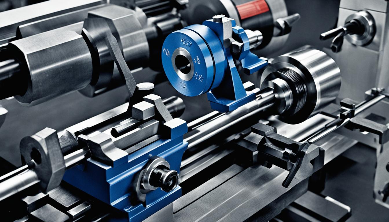
In precision manufacturing, the terms ‘lathe’ and ‘turning machine’ are frequently used interchangeably, often causing confusion for those new to the field. Fundamentally, both refer to machine tools designed to remove material from a rotating workpiece, creating objects with rotational symmetry. While ‘lathe’ is a traditional term, ‘turning machine’ often encompasses more advanced, automated systems, particularly in modern industrial contexts.
Defining Lathe and Turning Machine Terminology
Historically, the term ‘lathe’ has been used for centuries to describe a machine that rotates a workpiece against a cutting tool. This foundational concept remains central to all rotational machining. Early lathes were manually operated, shaping wood and metal with remarkable skill.
Contemporary industrial practice often uses ‘turning machine’ as a broader, more encompassing term, especially when referring to Computer Numerical Control (CNC) equipment. A CNC turning machine, or CNC turning center, represents an evolution of the traditional lathe, integrating advanced automation and multi-axis capabilities.
While a basic lathe might primarily perform turning operations on two axes, a modern turning center can incorporate additional axes (Y, C, B) and ‘live tooling’ for milling, drilling, and tapping. This expanded functionality blurs the lines, making ‘turning machine’ a suitable descriptor for these versatile, multi-tasking systems.
Fundamental Principles of Rotational Machining
| Machine Type | Primary Function | Typical Axes | Key Capabilities |
|---|---|---|---|
| Manual Lathe | Basic turning, facing, drilling | 2 (X, Z) | Operator-controlled, versatile for small batches, prototyping |
| CNC Lathe | Automated turning, facing, boring, threading | 2-3 (X, Z, optional C) | Computer-controlled, higher precision, repeatability |
| CNC Turning Center | Multi-axis turning, milling, drilling, tapping | 3-5+ (X, Y, Z, C, B) | Live tooling, automatic tool changers, complex geometries |
| Turn-Mill Center | Combined turning and milling operations | 5+ (X, Y, Z, C, B) | Single-setup machining for highly complex parts, reduced cycle times |
Rotational workpiece cutting involves securing a workpiece and rotating it at high speed about a central axis. A cutting tool, typically a single-point tool, is then brought into contact with the rotating material. This controlled interaction removes material in the form of chips.
The kinematic principle is straightforward: the workpiece spins, and the tool moves linearly along controlled paths. This relative motion allows for the creation of various cylindrical, conical, or spherical shapes. The process is critical for producing components requiring precise rotational symmetry.
Material removal generates significant heat at the cutting zone, necessitating proper cooling strategies. Chip formation is also a crucial aspect, as efficient chip evacuation prevents tool rubbing, overheating, and potential damage to the workpiece or tool.
Essential Lathe Machine Construction Elements
Every lathe, regardless of its complexity, relies on several core structural components. The bed forms the rigid foundation, supporting all other elements and maintaining their alignment. It is typically made from heavy cast iron to absorb vibrations and resist deflection during cutting.
The headstock, mounted on the bed, houses the main spindle, motor, and speed control system. The spindle is responsible for rotating the workpiece, which is typically held by a chuck or collet. Spindle rigidity and bearing configuration are paramount for machining accuracy.
Opposite the headstock, the tailstock provides support for longer workpieces, preventing deflection during machining. It can also be fitted with drilling tools for axial operations. The carriage, which moves along the bed’s ways, carries the cross-slide and tool post, enabling precise tool positioning.
Modern CNC turning centers integrate these fundamental components within an enclosed setup, often featuring advanced linear guideways for enhanced precision and repeatability. These machines also include sophisticated control systems and automatic tool changers, significantly boosting productivity.
Comprehensive Overview of Turning Operations
Turning encompasses a variety of operations, each designed to achieve specific geometric features on a rotating workpiece. Basic ‘straight turning’ reduces the diameter of a cylindrical part. ‘Facing’ involves cutting the end of the workpiece to create a flat, perpendicular surface.
Other common operations include ‘boring,’ which enlarges an existing hole, and ‘threading,’ which cuts helical grooves for screws or bolts. ‘Knurling’ creates a textured pattern on the surface for improved grip, while ‘grooving’ cuts channels into the workpiece.
Specialized turning operations, such as ‘taper turning’ for conical shapes or ‘profiling’ for complex contours, are also routinely performed. The selection of the appropriate cutting tool and its geometry is critical for efficient material removal and achieving the desired surface finish.
Modern Industrial Turning Machinery and Capabilities
Industrial turning machinery has evolved significantly, with CNC turning centers leading modern manufacturing. These advanced machines offer high accuracy, efficiency, and the ability to produce complex components with minimal human intervention. They are often enclosed for safety and chip management.
Multi-tasking machines, often called ‘turn-mill centers,’ combine turning with milling, drilling, and tapping operations in a single setup. This capability reduces setup times and improves overall efficiency by eliminating the need to transfer parts between different machines.
Automation, including robotic integration for loading and unloading, further enhances the productivity of turning centers. These machines can operate with multiple axes (up to 5 or 6), allowing for the creation of intricate geometries and optimized tool paths.
Precision, Tolerances, Feeds, and Speeds in Turning
Achieving precision in turned parts requires adherence to strict tolerances. ISO 2768 is a widely used international standard that defines general tolerances for linear and angular dimensions when specific tolerances are not explicitly stated on engineering drawings.
The ISO 2768 standard includes different tolerance classes, such as ‘fine (f)’ for high-precision requirements and ‘medium (m)’ for general-purpose applications. For metal parts, standard tolerances often fall around ±0.005 inches (0.13 mm), though tighter tolerances down to ±0.0001 inches are achievable with advanced CNC turning centers.
Feeds and speeds are critical parameters that directly impact surface finish, tool life, and material removal rates. These values depend heavily on the workpiece material, cutting tool material and coating, machine rigidity, and desired surface finish.
- For 6061 Aluminum (Carbide Tooling):
- Cutting Speed (SFM): 600-1200 SFM for general purpose, 300-800 SFM for milling.
- Feed Rate (IPR): 0.004-0.010 IPR for roughing, 0.001-0.005 IPR for finishing.
- For 304 Stainless Steel (Coated Carbide Tooling):
- Cutting Speed (m/min): 150-220 m/min (approx. 490-720 SFM).
- Feed Rate (mm/rev): 0.20-0.40 mm/rev for roughing, 0.05-0.15 mm/rev for finishing.
These are starting points, and adjustments are often necessary based on specific machine conditions, tool geometry, and coolant strategies. For instance, flood coolant is essential for 304 stainless steel to manage heat and aid chip breaking.