
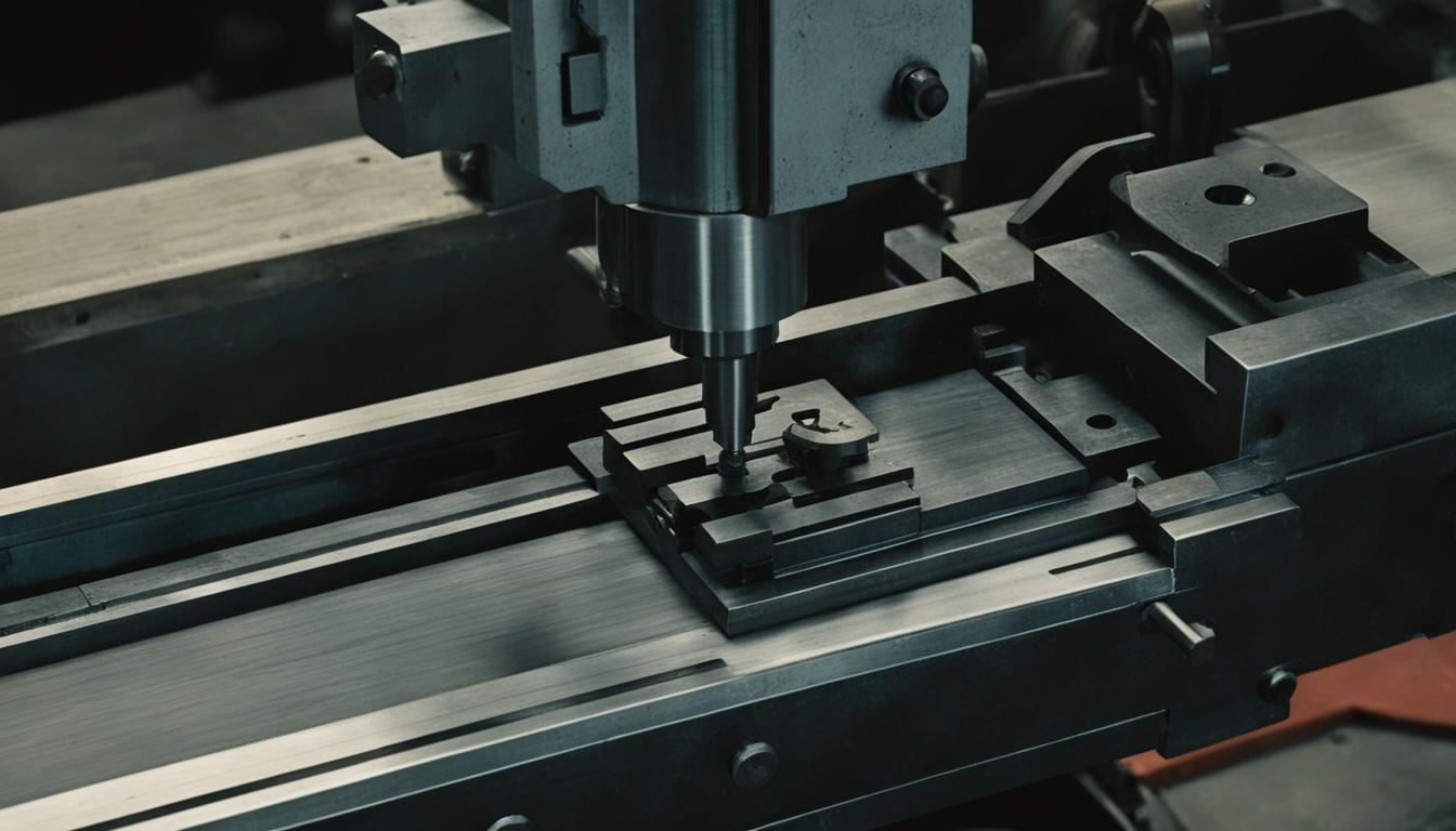
Manual milling machines remain fundamental in many workshops, offering direct operator control over material removal processes. These robust machines rely on mechanical linkages and precise adjustments to shape workpieces, demanding a thorough understanding of their operational mechanics for effective use.
Operating a manual mill involves coordinating several independent movements, each controlled by a dedicated mechanism. Precision in machining is achieved through the operator’s skill in manipulating these controls and interpreting visual feedback from the cutting action and workpiece.
Handwheel Lead Screw Control
Translating rotational input into linear motion is the primary function of the handwheel lead screw system on a manual milling machine. Each axis (X, Y, and sometimes Z for the knee) features a handwheel directly coupled to a lead screw, which engages with a fixed nut within the machine’s structure. Rotating the handwheel advances or retracts the lead screw, moving the corresponding machine component, such as the table or saddle.
Lead screws typically feature Acme threads, designed for strength and efficient power transmission. Common pitches vary, but a 5 TPI (threads per inch) lead screw is frequently encountered, meaning one full rotation of the handwheel moves the table 0.200 inches. Dial graduations on the handwheel provide finer resolution, often marked in increments of 0.001 inches, allowing for precise positional adjustments.
Backlash, the play between the lead screw and its nut, is an inherent characteristic of these mechanical systems. It manifests as a small amount of handwheel rotation that does not immediately translate into table movement. Operators must compensate for backlash, particularly when changing direction, by overshooting the desired position and then approaching it from a consistent direction to ensure accuracy.
Modern manual mills sometimes incorporate anti-backlash nuts or double-nut systems to minimize this play, enhancing precision. However, even with these improvements, careful operational technique remains crucial for maintaining tight tolerances, especially during climb milling operations where cutter forces can exacerbate backlash effects.
Knee Elevation Movement
| Parameter | Typical Value/Range | Notes |
|---|---|---|
| Lead Screw Pitch | 5 TPI (0.200″ per rev) | Common for X/Y axes |
| Spindle Taper | R8, CAT40, BT40 | Depends on machine size/type |
| Spindle Runout | < 0.0005" (0.0127 mm) | Measured at tool holder |
| Table T-Slot Width | 5/8″ (15.875 mm) | Standard for workholding |
| General Machining Tolerance | ±0.002″ to ±0.005″ | Achievable with skilled operator and good machine |
Vertical positioning of the workpiece relative to the spindle is managed by the knee elevation mechanism. The knee, a substantial casting, supports the saddle and table assembly, allowing the entire workholding platform to move up and down along the machine’s column. This movement is critical for setting the initial cutting depth and accommodating different workpiece heights.
An elevating screw, often a large diameter Acme thread, runs vertically through the column and engages with a nut within the knee. A handwheel, typically located on the front of the machine, drives this screw, often through a set of bevel gears to change the axis of rotation. Locking mechanisms, usually large clamping levers, secure the knee firmly in position once the desired height is achieved, preventing any unintended vertical movement during machining.
The stability of the knee is paramount for machining accuracy. Its robust construction and secure locking ensure that heavy workpieces and significant cutting forces do not induce deflection or vibration. Proper lubrication of the elevating screw and column ways is essential for smooth, precise movement and to minimize wear over time.
Quill Feed Manual Spindle
The quill provides the spindle with a controlled vertical travel independent of the knee, primarily used for drilling, boring, and light milling operations. This mechanism allows the cutting tool to be fed into the workpiece without altering the overall knee height, offering fine control over depth of cut for specific features.
A rack and pinion system typically drives the quill’s movement. A hand lever provides rapid coarse feed for drilling, while a separate fine feed handwheel, often worm-gear driven, offers precise control for boring or sensitive operations. The spindle itself is housed within the quill and features a standard taper, such as R8 for smaller machines or CAT40/BT40 for larger ones, to accept various tool holders.
Spindle speeds are adjusted either through a variable speed drive, allowing continuous adjustment, or by manually changing belt positions on stepped pulleys. Maintaining proper spindle runout is critical for tool life and surface finish; a typical acceptable runout for a well-maintained manual mill spindle is often less than 0.0005 inches (0.0127 mm) at the tool holder.
Feeds and speeds for manual milling are determined by material, tool type, and desired surface finish. For instance, drilling 6061 aluminum with a high-speed steel (HSS) drill might involve a surface speed of 200-300 SFM and a feed rate of 0.002-0.005 inches per revolution, while drilling mild steel would require lower speeds and similar feeds.
Operator Visual Alignment
Achieving accurate workpiece positioning and tool alignment on a manual mill heavily relies on the operator’s visual acuity and the use of specialized tools. Before any cutting begins, the machine’s head must be ‘trammed’ to ensure the spindle is perfectly perpendicular to the table surface. This process involves using a dial indicator mounted in the spindle to sweep across the table, adjusting the head until the indicator reads zero deviation across its travel.
Locating workpiece edges or features precisely is accomplished with tools like edge finders, wigglers, and dial test indicators. An edge finder, for example, uses a spring-loaded tip that ‘kicks’ when it contacts the workpiece edge, indicating the exact position. These methods allow the operator to establish a precise datum for subsequent machining operations.
Digital Readouts (DROs) significantly enhance visual alignment by providing real-time, high-resolution numerical displays of the table’s position along each axis. While not strictly ‘visual’ in the traditional sense, DROs eliminate reliance on reading fine handwheel dials, drastically reducing human error and speeding up setup times, making them an indispensable upgrade for many manual mills.
Mechanical Table Positioning
The milling machine’s table provides the platform for securing the workpiece and facilitates its movement in the X (longitudinal) and Y (traverse) axes. This mechanical positioning system is built for rigidity and precision, allowing the operator to guide the cutting tool across the material with controlled movements.
The table slides on the saddle (Y-axis), which in turn slides on the knee (X-axis). These movements are guided by precision-ground ways, typically dovetail or box ways, which ensure linear travel. Adjustable gibs, tapered strips of metal, are fitted between the moving components and the ways. These gibs allow for fine tuning of the fit, compensating for wear and eliminating play, which is crucial for maintaining machining accuracy.
Table locks are essential clamping mechanisms that secure the table and saddle in position once a desired coordinate is reached. Engaging these locks prevents any unintended movement during heavy cuts, preserving the accuracy of the machined feature. Neglecting to engage table locks can lead to chatter, poor surface finish, and dimensional inaccuracies.
Standard T-slots, typically 5/8 inch (15.875 mm) wide, are machined into the table surface to accommodate various workholding devices such as vises, clamps, and fixtures. The table’s load capacity varies significantly by machine size, but even smaller benchtop mills can often support hundreds of pounds, while larger industrial models can handle thousands.