
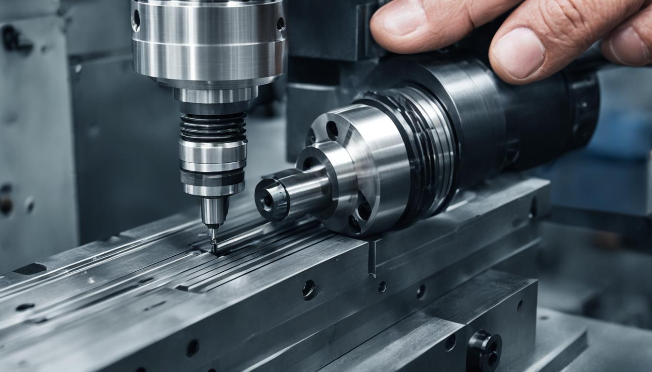
CNC milling and turning represent fundamental subtractive manufacturing processes, each employing distinct kinematic principles to shape raw material into finished components. While both rely on computer numerical control (CNC) for automated precision, their operational mechanics dictate the types of geometries they can efficiently produce and the tooling required. Understanding these core differences is essential for optimal part design and manufacturing strategy.
Fundamental Kinematics: Tool vs. Workpiece Rotation
The primary distinction between milling and turning lies in which element rotates during the material removal process. In CNC milling, the cutting tool itself rotates at high speeds, while the workpiece remains stationary, typically clamped securely to a machine table. The rotating multi-point cutting tool then moves along various axes to engage and remove material from the fixed workpiece.
Conversely, CNC turning involves a stationary, single-point cutting tool that engages a workpiece rotating at high RPMs. The workpiece is held in a chuck or collet and spins about its own axis, while the cutting tool traverses along linear paths to remove material. This rotational motion of the workpiece is fundamental to creating cylindrical and conical geometries.
This difference in kinematic setup directly influences the types of parts each machine is best suited for. Milling’s rotating tool and stationary workpiece allow for intricate features on flat or complex surfaces, whereas turning’s rotating workpiece naturally generates parts with rotational symmetry.
Machining Geometry: Flat/3D Milling vs. Cylindrical Turning
| Parameter | CNC Milling (Typical) | CNC Turning (Typical) |
|---|---|---|
| Primary Rotating Element | Cutting Tool | Workpiece |
| Standard Tolerances | ±0.005″ (±0.127 mm) | ±0.005″ (±0.127 mm) |
| High Precision Tolerances | ±0.001″ to ±0.002″ (±0.0254 to ±0.0508 mm) | ±0.001″ to ±0.002″ (±0.0254 to ±0.0508 mm) |
| Aluminum Milling RPM (e.g., 6061) | 8,000–12,000 RPM | N/A (Workpiece RPM) |
| Aluminum Milling Feed Rate | 40–80 IPM (1000–2000 mm/min) | N/A (Workpiece RPM) |
| Steel Turning Cutting Speed | N/A (Tool RPM) | 80-150 m/min |
| Steel Turning Feed Rate | N/A (Tool RPM) | 0.1–0.4 mm/rev (varies by depth/finish) |
| Typical Surface Finish (Ra) | 1.6 to 6.3 µm (fine milling 0.8 µm) | 0.8 to 3.2 µm (can be finer) |
CNC milling excels at producing flat surfaces, pockets, slots, and complex three-dimensional contours. The cutting tool’s ability to move along multiple axes enables the creation of prismatic shapes, irregular geometries, and features like angled holes or deep cavities.
Turning, by contrast, is inherently designed for generating cylindrical, conical, and spherical forms. Operations such as facing, boring, grooving, and threading are standard on a lathe, all relying on the workpiece’s rotation to achieve concentric features.
While modern mill-turn machines can combine both capabilities, a dedicated CNC mill is optimized for non-cylindrical parts, and a dedicated CNC lathe is optimized for parts dominated by rotational surfaces.
Axis Control and Complexity: Multi-Axis vs. 2-Axis Focus
Standard CNC milling machines typically operate with three linear axes (X, Y, Z), allowing movement across a flat plane and depth control. More advanced milling centers incorporate additional rotary axes, such as 4-axis and 5-axis configurations. A 4-axis machine adds one rotary axis, often rotating the workpiece, while a 5-axis machine introduces a second rotary axis, providing greater positioning freedom for the tool to approach the part from various angles.
Multi-axis milling significantly reduces the need for multiple setups, improves access to angled features, and enhances surface continuity on complex contours, making it ideal for aerospace, medical, and mold-making industries.
Conversely, a basic CNC lathe, often referred to as a 2-axis lathe, primarily utilizes the X and Z axes. The X-axis controls the tool’s radial movement (diameter), and the Z-axis controls its longitudinal movement (length) along the workpiece’s rotational axis. This configuration is highly efficient for producing simple cylindrical parts like shafts, pins, and fittings.
While 2-axis lathes are cost-effective for high-volume production of symmetrical components, more advanced turning centers can integrate additional axes, including a C-axis for workpiece rotation control and Y-axis for off-center milling or drilling with ‘live tooling,’ blurring the lines between turning and milling capabilities.
Cutting Tool Design: End Mills vs. Single-Point Inserts
Milling operations predominantly utilize multi-flute end mills, which are rotating tools with cutting edges on their periphery and often on their end. Common types include square end mills for flat surfaces and slots, ball nose end mills for curved surfaces and 3D contours, and corner radius end mills for improved edge durability.
These tools are typically made from high-speed steel (HSS) or carbide, with carbide being preferred for its durability and heat resistance, especially in aluminum machining. Coatings like ZrN or DLC are often applied to carbide end mills to reduce friction and prevent material adhesion, particularly with aluminum.
Turning, on the other hand, primarily employs single-point cutting tools, often in the form of indexable carbide inserts. These inserts feature a single, precisely ground cutting edge that engages the rotating workpiece. Insert geometries vary significantly, with shapes like square, triangular, and rhombic (80° or 55°) being common, each selected based on the required strength, versatility, and chip control for roughing, medium, or finishing operations.
The nose radius of a turning insert is a critical parameter, influencing surface finish and tool strength. Larger nose radii generally provide better surface finishes and stronger cutting edges but can increase cutting forces.
Resultant Part Geometry: Output Shapes and Applications
The inherent mechanics of milling allow for the creation of complex, non-symmetrical parts with intricate features. This includes components with multiple flat surfaces, deep pockets, slots, chamfers, and highly detailed 3D contours. Industries such as aerospace, automotive, and mold manufacturing heavily rely on milling for parts like engine blocks, brackets, impellers, and complex housings.
Turning is best suited for parts with rotational symmetry. This encompasses a wide range of components such as shafts, pins, bushings, flanges, and threaded rods. The process is highly efficient for producing precise diameters, lengths, and concentric features, making it a staple in industries requiring cylindrical components like hydraulic fittings, motor shafts, and valve bodies.
Many modern parts, however, require a combination of both milling and turning operations, leading to the increased adoption of ‘mill-turn’ or ‘multi-tasking’ machines that integrate both capabilities into a single setup, reducing lead times and improving accuracy by eliminating re-fixturing.
Performance Metrics: Tolerances, Feeds, and Speeds
Achieving precise dimensions and optimal surface finishes in both milling and turning requires careful control of machining parameters. Standard CNC machining tolerances typically range from ±0.005 inches (±0.127 mm) for most metals. For high-precision applications, both milling and turning can achieve tighter tolerances, often around ±0.001 to ±0.002 inches (±0.0254 to ±0.0508 mm), with specialized techniques reaching micron-level precision.
Feeds and speeds, defined by spindle RPM and feed rate (IPM or mm/min), are critical for chip formation, heat management, tool life, and surface finish. These parameters are highly dependent on the material, tool geometry, and machine rigidity.
For instance, milling aluminum often utilizes higher RPMs (8,000–12,000 RPM) and moderate feed rates (40–80 IPM) with carbide end mills to prevent built-up edge and ensure efficient chip evacuation. Turning steel typically involves lower cutting speeds but can achieve excellent surface finishes due to continuous cutting action.