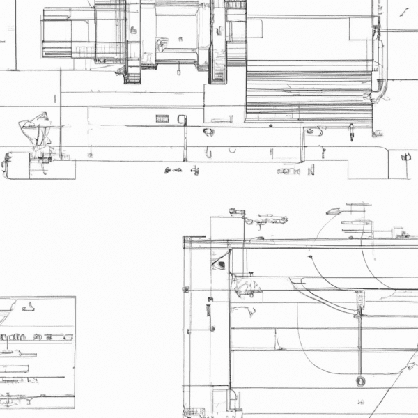
Even with advanced technology, technical drawings remain essential for sourcing parts with accuracy and efficiency. In this blog, we will explore the importance of technical drawings, their anatomy, the significance of notes to manufacturers, and provide expert tips for preparing flawless technical drawings for CNC machining.
Why are technical drawings still important for sourcing parts?
Technical drawings serve as the fundamental communication link between designers, engineers, and manufacturers. They provide a comprehensive representation of a part’s specifications, dimensions, tolerances, and material requirements. While CNC machines are highly advanced, they still rely on precise instructions to produce the desired output. Technical drawings ensure that the manufacturer understands the design intent, eliminating guesswork and reducing the risk of errors during the production process.
What is the anatomy of a technical drawing?
A typical technical drawing comprises several key elements that convey vital information about the part. These elements include:
- Title Block: Contains essential details such as the drawing title, part number, revision number, date, and the name of the designer or engineer.
- Views: Orthographic projections (e.g., top, front, side) showing different perspectives of the part.
- Dimensions and Tolerances: Accurate measurements of the part’s features, along with permissible variations to ensure proper fit and function.
- Geometric Dimensioning and Tolerancing (GD&T): A symbolic language used to specify complex tolerances and geometric relationships between features.
- Bill of Materials (BOM): A list of all the components required to assemble the final product.
What are notes to the manufacturer and why do you need them?
Notes to the manufacturer are essential annotations on the technical drawing that provide additional information or instructions. They offer crucial insights that might not be evident from the drawing alone. These notes can include specific manufacturing processes, material specifications, surface finishes, assembly instructions, or any other relevant details that aid the manufacturer in producing the part accurately and efficiently. Clear and concise notes to the manufacturer reduce the chances of misinterpretation and increase the likelihood of a successful manufacturing process.
How to prepare a technical drawing in 7 simple steps
Preparing a technical drawing for CNC machining requires attention to detail and a methodical approach. Here are seven simple steps to guide you through the process:
Step 1: Define the Objective: Clearly understand the purpose of the part and its intended function.
Step 2: Gather Necessary Information: Collect all relevant data, including design specifications, critical dimensions, and material requirements.
Step 3: Select the Views: Choose appropriate orthographic views to fully represent the part’s geometry.
Step 4: Dimensioning and Tolerancing: Apply accurate and consistent dimensions with appropriate tolerances to ensure the part meets the desired quality standards.
Step 5: Add GD&T Symbols (if applicable): Use GD&T symbols to convey complex geometric requirements and tolerances.
Step 6: Include the Bill of Materials (BOM): List all components necessary for the assembly of the final product.
Step 7: Review and Validate: Thoroughly review the technical drawing for errors or omissions before sending it for manufacturing.

How do you add critical dimensions to technical drawings?
Critical dimensions are the most vital measurements that directly impact the functionality and performance of the part. To ensure these dimensions are clear and easily identifiable on the technical drawing, consider the following tips:
- Highlight Critical Dimensions: Use thicker lines or circles to emphasize critical dimensions, drawing attention to their importance.
- Organize Dimensions Logically: Arrange dimensions in a clear and logical manner, avoiding clutter and confusion.
- Use GD&T for Complex Geometries: For intricate features, consider using GD&T symbols to communicate precise tolerances effectively.
- Provide Tolerance Callouts: Clearly specify the allowed variations for critical dimensions to avoid ambiguity during manufacturing.
- Add Notes for Clarity: Use notes to the manufacturer to explain the significance of critical dimensions and their impact on the overall part performance.
By following these expert tips, you can master the art of preparing flawless technical drawings for CNC machining. These drawings act as the backbone of the manufacturing process, facilitating smooth communication between design and production teams and ultimately leading to high-quality, accurately manufactured parts.
Hole callouts are crucial for providing detailed information about holes in a technical drawing. To add hole callouts effectively, follow these steps:
- Identify Holes: Clearly mark each hole on the drawing using circles or other symbols.
- Specify Hole Type: Indicate the type of hole (e.g., counterbore, countersink, threaded) using standard symbols.
- Provide Hole Dimensions: Include the diameter, depth, and any other relevant dimensions of the hole.
- Callout Format: Present the hole callout in a structured format, such as “Hole Diameter – Depth.”
- Tolerance and GD&T: Apply appropriate tolerances and GD&T symbols if necessary to define the allowable variations for the holes.
How do you add threads to a technical drawing?
Adding threads to a technical drawing is essential for components that require threaded connections. Here’s how to do it:
- Thread Specification: Clearly specify the type of thread (e.g., UNC, UNF, metric) and the thread pitch.
- Thread Representation: Depict the threads using standard thread symbols. For detailed threads, provide a section view to show the thread profile accurately.
- Thread Length: Indicate the length of the threaded portion, especially if it’s different from the overall length of the part.
- Thread Callout: Include a callout that clearly identifies the threaded feature and provides all necessary thread information.
How do you specify tolerances in a technical drawing?
Specifying tolerances is critical to ensure the manufacturability and functionality of a part. To specify tolerances effectively:
- Use Standard Symbols: Utilize standard tolerance symbols like “+/-” for bilateral tolerance or “±” for unilateral tolerance.
- Apply GD&T for Complex Tolerances: For more intricate tolerances or geometric relationships, use GD&T symbols and controls.
- Define Tolerance Zones: Clearly define the tolerance zones on the drawing, indicating the permissible variations for each feature.
- Consider Manufacturing Process: Take into account the capabilities of the manufacturing process and set tolerances accordingly.
- Balancing Tolerances: Balance the tolerances to avoid excessive costs or conflicts in the assembly process.
What is Geometric Dimensioning & Tolerancing (GD&T)?
Geometric Dimensioning and Tolerancing (GD&T) is a symbolic language used to communicate complex tolerances and geometric relationships on a technical drawing. It provides a more precise and comprehensive way to define part requirements than traditional linear dimensions and tolerances. GD&T includes symbols, feature controls, datum references, and modifiers to convey specific tolerances for form, orientation, location, and profile of features. GD&T ensures that the part can be manufactured, assembled, and function as intended, regardless of the manufacturing method used.
Frequently Asked Questions
Q1: Can I use CAD software for creating technical drawings?
Yes, Computer-Aided Design (CAD) software is commonly used to create technical drawings. CAD tools offer various features that simplify the drawing process, such as automated dimensioning, standardized symbols, and the ability to store and manage design data efficiently.
Q2: What are some common mistakes to avoid when preparing technical drawings?
Some common mistakes to avoid include unclear or missing dimensions, inconsistent tolerances, using non-standard symbols, and omitting critical notes to the manufacturer. It’s essential to thoroughly review and validate the drawing before sending it for manufacturing.
Q3: Are there international standards for technical drawings?
Yes, several international standards govern technical drawings. The most widely used standard is ISO 128, which defines the general principles of presentation for technical drawings. For GD&T, ISO 1101 and ASME Y14.5 are widely recognized standards.
Q4: Can GD&T reduce manufacturing costs?
Yes, GD&T can help reduce manufacturing costs by specifying tolerances more effectively, which leads to a higher yield rate in production and fewer rejected parts. GD&T can optimize part functionality, allowing for less stringent requirements on non-critical features, leading to cost savings.
Books to read to expand knowledge
Whether you are a seasoned professional or a newcomer to the field, mastering CNC machining requires access to valuable resources that deepen your understanding of the subject. One of the best ways to acquire in-depth knowledge is through books that delve into the intricacies of CNC machining. Here are some highly recommended books that can take your CNC skills to the next level:
- “CNC Programming Handbook” by Peter Smid
- Available at: Amazon
- This book is regarded as a definitive guide to CNC programming and machining.
- It covers everything from basic concepts to advanced programming techniques.
- Suitable for beginners and experienced professionals alike.
- Reader Review: “This book has become my go-to reference for CNC programming. It covers a wide range of topics with clear explanations and practical examples. It’s a must-have for anyone in the CNC machining industry.” – John D.
- “CNC Machining Handbook: Building, Programming, and Implementation” by Alan Overby
- Available at: McGraw-Hill
- Offers a comprehensive understanding of CNC machining from design to implementation.
- Provides valuable insights into CNC software and programming languages.
- Suitable for intermediate and advanced learners seeking hands-on knowledge.
- Reader Review: “This book is a gem for anyone looking to deepen their CNC knowledge. The author’s approach to explaining complex concepts in a clear and concise manner is commendable. I’ve learned a lot from this book!” – Sarah L.
- “CNC Control Setup for Milling and Turning” by Peter Smid
- Available at: Industrial Press
- Focuses on the setup and operation of CNC machines for milling and turning processes.
- Covers practical techniques for optimizing CNC performance.
- Ideal for professionals seeking to enhance their setup skills.
- Reader Review: “This book is a game-changer! Peter Smid’s knowledge shines through in every chapter, and the tips and tricks he shares have immensely improved my CNC setup efficiency.” – Mark R.
- “CNC Trade Secrets: A Guide to CNC Machine Shop Practices” by James Harvey
- Available at: Amazon
- Offers a wealth of practical knowledge and insider tips for CNC machine shop practices.
- Focuses on real-world applications and problem-solving techniques.
- Suitable for beginners looking to bridge the gap between theory and practice.
- Reader Review: “This book is a goldmine! The author’s experience and expertise are evident in the invaluable trade secrets shared throughout the book. It’s an indispensable resource for anyone involved in CNC machining.” – Thomas B.
These books serve as excellent companions for individuals aiming to master CNC machining. They cover a wide range of topics, from programming and setup to real-world applications, offering a comprehensive understanding of the subject.
