
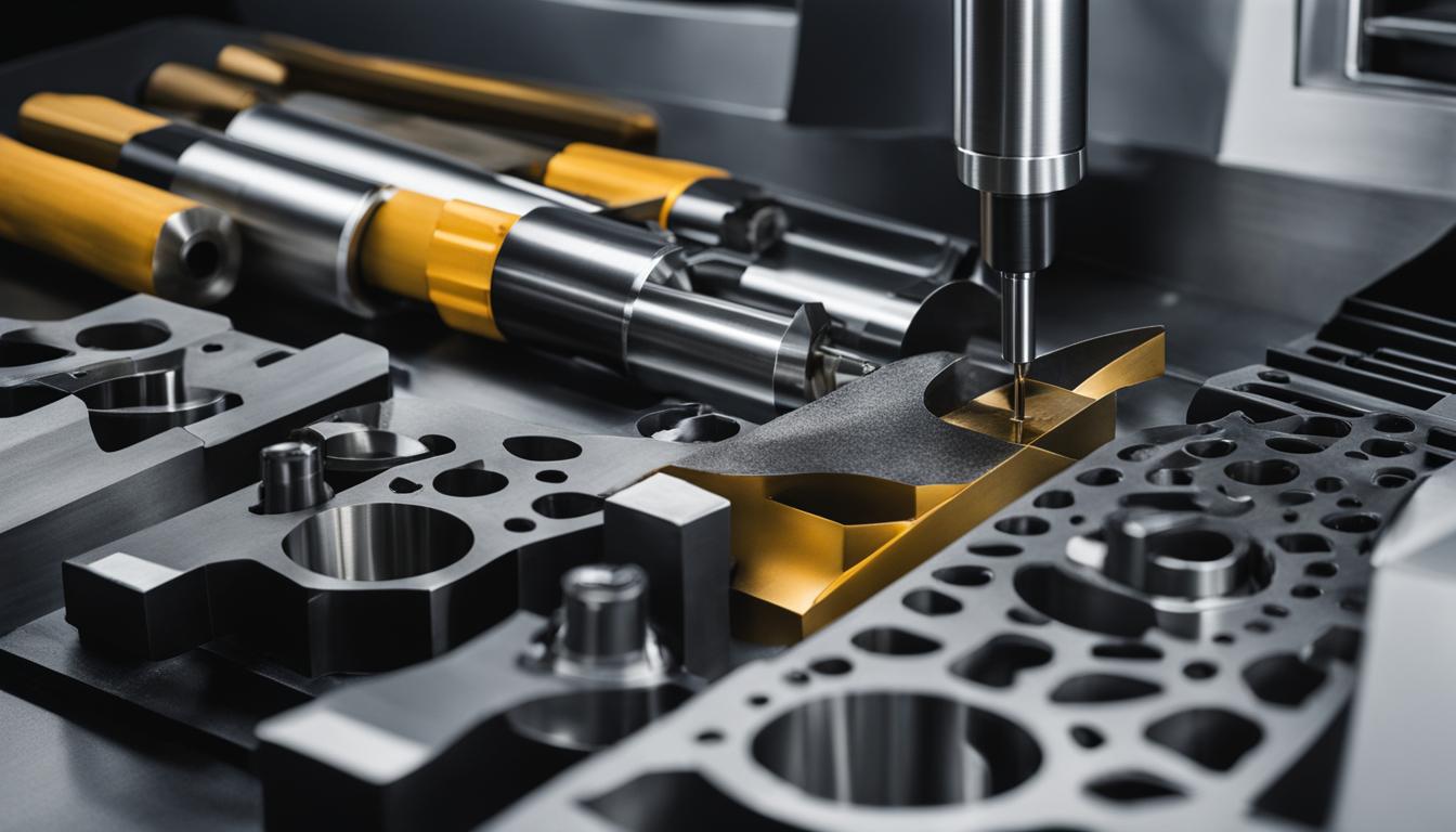
Subtractive manufacturing processes, such as turning and milling, are fundamental to modern industrial production. Both methods precisely remove material from a workpiece to achieve a desired geometry, yet they employ distinct kinematic principles and tooling strategies. Understanding these differences is crucial for engineers and machinists to select the optimal process for specific part requirements.
These machining techniques are essential for creating components across diverse industries, including aerospace, automotive, and medical device manufacturing. Each process offers unique advantages in terms of part geometry, surface finish, and production efficiency, making their proper application a cornerstone of precision manufacturing.
Fundamental Kinematics: Part vs. Tool Rotation
Turning operations are characterized by a rotating workpiece and a stationary, or linearly moving, cutting tool. The workpiece, typically cylindrical or bar stock, is securely held in a chuck or collet and rotated at high speeds by the machine’s spindle. Material removal occurs as a single-point cutting tool engages the spinning part, generating axisymmetric features.
Conversely, milling involves a rotating cutting tool that removes material from a workpiece that is generally held stationary or moves along multiple axes. The multi-flute cutter, such as an end mill, is mounted in the machine’s spindle and rotates at high RPMs, while the workpiece is fed into the tool. This setup allows for the creation of complex, non-axisymmetric shapes and features.
The primary distinction lies in which element provides the rotational motion for material removal. In turning, the workpiece spins, while in milling, the cutting tool rotates. This fundamental difference dictates the types of geometries each process can efficiently produce.
Machine Architecture: Lathes and Milling Centers
| Parameter | CNC Turning (Steel) | CNC Milling (Aluminum 6061) |
|---|---|---|
| Typical Spindle Speed (RPM) | 1100-1200 RPM (for 50mm diameter, Vc 180 m/min) | 8,000–12,000 RPM |
| Typical Feed Rate (Roughing) | 0.25–0.45 mm/rev | 40–80 IPM (1000-2000 mm/min) |
| Typical Feed Rate (Finishing) | 0.05–0.15 mm/rev | 0.001–0.005 inch chip load per tooth |
| Standard Tolerance | ±0.005 inches (±0.127 mm) | ±0.005 inches (±0.127 mm) |
| Tight Tolerance | ±0.001 inches (±0.025 mm) | ±0.001 inches (±0.025 mm) |
| Common Materials | Steel, Aluminum, Brass, Plastics | Aluminum, Stainless Steel, Brass, Titanium, Plastics |
Lathes are the primary machines used for turning operations. Modern CNC lathes range from basic 2-axis machines, capable of outer/inner diameter machining, facing, drilling, and tapping, to multi-axis turning centers. These advanced machines can incorporate live tooling, sub-spindles, and dual turrets, enabling complex operations like milling and boring within a single setup.
Milling machines, also known as machining centers, utilize rotating multi-point cutting tools. Common types include Vertical Machining Centers (VMCs) and Horizontal Machining Centers (HMCs). VMCs have a vertically oriented spindle, offering excellent visibility, while HMCs feature a horizontal spindle and often use rotary pallet systems for efficient workpiece changes.
Multi-axis CNC milling machines, with 3, 4, 5, or more axes, provide greater flexibility for intricate geometries, deep channels, and complex contours. These machines are essential for producing parts with features that would be impossible or highly inefficient with simpler setups.
Geometric Outcomes: Cylindrical vs. Prismatic Forms
Turning is inherently suited for producing cylindrical, conical, or other rotationally symmetrical parts. Operations like turning external diameters, facing flat surfaces, boring internal holes, and threading are core capabilities. The continuous rotational motion of the workpiece ensures concentricity and smooth surface finishes on these types of components.
Milling, conversely, excels at creating parts with complex shapes, flat surfaces, curved contours, and multiple features. It is ideal for operations such as face milling, contouring, drilling, slotting, and pocketing. This versatility makes milling indispensable for components like brackets, housings, and intricate molds that require non-axisymmetric geometries.
The choice between turning and milling often depends directly on the required part geometry. If the design demands a cylindrical component, turning is typically more efficient and cost-effective. For prismatic or highly complex forms, milling offers the necessary flexibility.
Cutting Tool Dynamics: Single-Point vs. Multi-Flute Cutting
Turning predominantly employs single-point cutting tools, where only one cutting edge engages the workpiece at any given moment. These tools consist of a sharpened point and a shank, designed for operations like turning, facing, and boring on a lathe. The geometry of a single-point tool includes specific rake and relief angles that influence cutting force, chip flow, and tool life.
Milling machines utilize multi-flute rotary cutters, such as end mills, which have multiple cutting edges that simultaneously or sequentially remove material. This design allows for higher material removal rates and more complex tool paths compared to single-point tools. Common milling tools include end mills, face mills, drills, and reamers.
The selection of cutting tool material, such as high-speed steel (HSS) or carbide inserts, is critical for both processes, impacting cutting speed, feed rates, and overall tool longevity. Modern tooling often features advanced coatings to enhance performance and extend tool life.
Distinct Subtractive Processes and Modern Engineering Practices
Both turning and milling are subtractive processes, meaning they create a part by removing material from a larger block or workpiece. However, their methodologies for material removal are fundamentally different. Turning shaves material from a rotating part, while milling carves material using a rotating tool.
Modern engineering practices leverage Computer Numerical Control (CNC) for both turning and milling, enabling high precision, repeatability, and automation. CNC systems translate digital design data into precise machine movements, coordinating tool rotation, axis movements, feed rates, and spindle speeds.
Standard tolerances for CNC machining typically range from ±0.005 inches (±0.127 mm) for most metals. For applications requiring greater accuracy, such as aerospace or medical components, precision tolerances of ±0.001 inches (±0.025 mm) or tighter can be achieved with specialized equipment and controlled conditions.
Feeds and speeds are critical parameters that must be carefully selected based on material, tool geometry, and machine rigidity. For aluminum, typical milling RPMs range from 8,000–12,000 with feed rates of 40–80 IPM. Steel turning operations might use a cutting speed (Vc) of 120–200 m/min with roughing feeds of 0.25–0.45 mm/rev.
Material selection significantly impacts machinability and achievable tolerances. Aluminum, known for its excellent machinability and corrosion resistance, is a highly versatile choice for milling. Stainless steel offers high strength and corrosion resistance, though it is harder to machine. For turning, materials like brass are favored for their malleability and conductivity.