
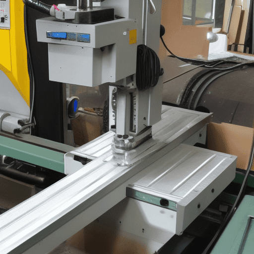
Computer Numerical Control (CNC) milling machines execute a diverse array of operations, transforming raw material into intricate components with high precision. These machines leverage multi-axis control and advanced tooling to perform subtractive manufacturing tasks, crucial across various industries.
Understanding the fundamental operations is essential for optimizing machining processes, selecting appropriate tooling, and achieving specified part tolerances and surface finishes. Each operation demands specific strategies and parameter considerations.
Face Milling Flat Surfaces
Face milling is a primary CNC operation designed to create flat, smooth surfaces perpendicular to the spindle axis. This process typically involves large-diameter cutters, known as face mills, equipped with multiple indexable inserts. The cutter’s diameter often exceeds the width of the workpiece, ensuring a clean, single pass or minimal step-over for wider surfaces.
Effective face milling requires careful selection of insert geometry, coating, and grade, tailored to the workpiece material. For instance, positive rake inserts are often preferred for aluminum, while negative rake inserts excel in harder materials like steel and stainless steel, offering greater edge strength.
Typical surface finish requirements for face-milled surfaces can range from 3.2 µm Ra (125 µinch Ra) for general purpose applications to 0.8 µm Ra (32 µinch Ra) or finer for sealing surfaces or mating components. Achieving these finishes depends heavily on feed per tooth, cutter runout, and coolant application.
Modern practices often incorporate high-feed face mills, which utilize small depth of cut and high feed rates to remove material rapidly, particularly in roughing operations. Standard flatness tolerances for CNC milled surfaces typically fall within 0.025 mm to 0.1 mm (0.001 to 0.004 inches) over a given length, depending on the part’s size and application.
End Milling Pockets
| Operation Type | Typical Dimensional Tolerance (mm) | Typical Surface Finish (Ra µm) |
|---|---|---|
| Face Milling (Rough) | ±0.1 to ±0.2 | 3.2 – 6.3 |
| Face Milling (Finish) | ±0.025 to ±0.075 | 0.8 – 1.6 |
| End Milling (Pocketing) | ±0.05 to ±0.125 | 1.6 – 3.2 |
| Drilling (Hole Diameter) | ±0.05 to ±0.2 | 3.2 – 6.3 |
| Rigid Tapping (Pitch Diameter) | ISO 6H/6g (varies) | N/A (thread quality) |
| Thread Milling (Pitch Diameter) | ISO 6H/6g (tighter possible) | N/A (thread quality) |
| Profile Contouring (General) | ±0.05 to ±0.1 | 1.6 – 3.2 |
| Profile Contouring (Fine) | ±0.01 to ±0.025 | 0.4 – 0.8 |
End milling pockets involves removing material from a confined area to create a cavity of a specific depth and geometry. This operation is fundamental for creating features like recesses, slots, and internal contours. Various end mill types, including flat, ball nose, and bull nose cutters, are employed based on the desired pocket floor and corner radii.
Pocketing strategies significantly impact machining efficiency and tool life. Trochoidal milling, for example, uses a circular tool path with a small radial depth of cut but a high axial depth of cut, effectively clearing chips and reducing heat buildup, especially in hard materials. This method minimizes tool engagement time, extending cutter life.
Climb milling is generally preferred for pocketing, as it directs cutting forces into the workpiece, producing a better surface finish and longer tool life compared to conventional milling. However, conventional milling can be advantageous for roughing operations on machines with backlash issues or for specific material properties.
Achieving tight tolerances in pockets, particularly for corner radii, often necessitates smaller diameter tools or multiple passes. Standard tolerances for pocket dimensions can range from ±0.05 mm to ±0.125 mm (±0.002 to ±0.005 inches), with tighter tolerances requiring more precise machine calibration and optimized tool paths.
Drilling and Rigid Tapping
Drilling creates cylindrical holes in a workpiece, a foundational operation in almost all machining processes. Spot drills initiate holes accurately, preventing ‘walking,’ followed by twist drills for through-holes or blind holes. Indexable insert drills offer high material removal rates for larger holes, while spade drills are suitable for deep holes.
Rigid tapping, also known as synchronous tapping, is a highly precise method for cutting internal threads. The CNC machine’s spindle rotation and Z-axis feed are perfectly synchronized, matching the tap’s pitch. This synchronization eliminates the need for a floating tap holder, reducing thread errors and tap breakage, especially in tough materials.
Proper tap selection is critical; cut taps remove material, while form taps (cold forming) displace material, producing stronger threads without chips. Thread engagement, typically 60% to 75%, balances thread strength with tapping torque requirements. Excessive engagement increases torque and tap breakage risk.
Coolant application is vital during drilling and tapping to dissipate heat, lubricate the cutting action, and evacuate chips. Through-tool coolant delivery is highly effective for deep holes and difficult-to-machine materials, ensuring consistent performance and extended tool life.
Thread Milling
Thread milling is an advanced CNC operation that uses a rotating cutter to generate internal or external threads through helical interpolation. Unlike tapping, which uses a single tool to form the entire thread in one pass, thread milling can produce various thread sizes and pitches with a single tool, offering significant flexibility.
This method is particularly advantageous for large diameter threads, hard materials, or when precise control over thread depth and quality is required. If a thread mill breaks, it can often be removed without damaging the workpiece, unlike a broken tap. It also allows for left-hand or right-hand threads with the same tool.
Programming thread milling involves helical interpolation, where the tool simultaneously moves in a circular path (X and Y axes) and advances axially (Z-axis) by the thread pitch per revolution. Multiple passes may be used for larger threads or harder materials to manage cutting forces and improve surface finish.
Feeds and speeds for thread milling are typically higher than for tapping, as the cutting action is distributed over multiple teeth. This reduces heat and stress on the tool. Thread quality and pitch diameter tolerances are often superior with thread milling, especially for critical applications.
Profile Contouring
Profile contouring involves machining the external or internal perimeter of a part to a specific shape, often with varying depths and complex curves. This operation is fundamental for creating intricate geometries, aesthetic features, and functional interfaces. It relies heavily on multi-axis control and sophisticated CAM software.
Tool selection for contouring is diverse, including flat end mills for vertical walls, ball end mills for smooth, sculpted surfaces, and bull nose end mills for combining flat floors with corner radii. The choice depends on the desired surface finish, geometry, and material removal requirements.
For 3D contouring, tool path strategies like ‘Z-level roughing,’ ‘scallop,’ and ‘spiral’ are employed to efficiently remove material and achieve the desired surface quality. Stepover and stepdown parameters are critical; smaller values result in finer surface finishes but increase machining time.
Achieving high-quality surface finishes, particularly on complex 3D contours, often requires multiple finishing passes with smaller tools and optimized tool paths. Modern CNC machines with high-speed machining capabilities can significantly reduce cycle times while maintaining excellent surface integrity.
Standard tolerances for contoured profiles can vary widely based on application, from ±0.1 mm (±0.004 inches) for general features to ±0.01 mm (±0.0004 inches) for precision components. The machine’s accuracy, tool deflection, and environmental factors all influence the achievable precision.