
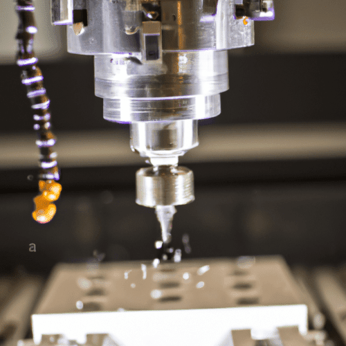
Milling machines are versatile subtractive manufacturing tools, capable of transforming raw material into complex geometries with high precision. These machines utilize rotating cutters to remove material from a workpiece, creating everything from flat surfaces to intricate shapes. Their adaptability makes them indispensable across various industries, including automotive, aerospace, and medical device manufacturing.
Modern CNC milling machines, in particular, offer exceptional accuracy and efficiency, automating operations with precise tool movements. Advancements in tooling, such as coated carbide end mills and optimized geometries, further enhance performance, durability, and material removal rates.
Surface Flattening and Planar Machining
Achieving a truly flat surface is a fundamental milling operation, often the first step in preparing a workpiece for subsequent machining. Face milling, using a face mill or a large-diameter end mill, is the primary method for this task. The goal is to create a smooth, consistent plane, removing material efficiently while maintaining tight flatness tolerances.
Standard flatness tolerances for milled surfaces can vary significantly based on application and machine capability, but precision machining often aims for deviations in the range of 0.0005 to 0.001 inches (0.0127 to 0.0254 mm) over a given area. Surface finish, measured in Ra (Roughness average), is also critical, with typical values for general machining ranging from 32 to 125 Ra, and finer finishes down to 16 Ra or better for critical applications.
For 6061 aluminum, a common starting cutting speed (Vc) for carbide end mills is around 300 m/min (approximately 984 SFM), with chip loads between 0.05-0.15 mm/tooth. When face milling 1018 mild steel with carbide inserts, cutting speeds typically range from 300-600 SFM. Aggressive feeds are often beneficial in steel to create thicker chips that carry heat away effectively.
Precision Pocketing and Cavity Creation
| Thread Size | Material | Recommended Tap Drill (mm / inch) | Tapping Speed (SFM) |
|---|---|---|---|
| M8 x 1.25 (Coarse) | 6061 Aluminum | 6.8 mm | 70-75 |
| M8 x 1.25 (Coarse) | 1018 Steel | 6.8 mm | 30-40 |
| 1/4″-20 UNC (Coarse) | 6061 Aluminum | 5.1 mm (0.201″) | 70-75 |
| 1/4″-20 UNC (Coarse) | 1018 Steel | 5.1 mm (0.201″) | 30-40 |
Pocketing involves removing material from a confined area to create a cavity of a specific shape and depth. This operation is crucial for manufacturing housings, molds, and various functional components. Effective pocketing requires careful consideration of tool selection, toolpath strategy, and chip evacuation.
End mills are the primary tools for pocketing, with different flute counts and geometries suited for roughing and finishing. Roughing passes prioritize material removal, often using aggressive depths of cut and radial engagements, while finishing passes focus on achieving the specified dimensions and surface finish. Tolerances for pocket dimensions can range from ±0.001 to ±0.005 inches (±0.025 to ±0.127 mm), depending on the part’s function and material.
For roughing pockets in 6061 aluminum with a 1/2″ (12.7mm) 3-flute carbide end mill, cutting speeds can be 800-1200 SFM (244-366 m/min) with chip loads of 0.004-0.008 IPT (0.10-0.20 mm/tooth). Finishing passes might use higher SFM (1000-1500+ SFM) and lower chip loads (0.002-0.004 IPT) to achieve a superior surface finish. For 1018 mild steel, a 1/2″ 4-flute solid carbide end mill might start at 400 SFM with a chip load of 0.002″ per tooth for roughing.
Accurate Drilling and Threading Operations
Drilling and tapping are fundamental milling capabilities for creating holes and internal threads. Precision in these operations is paramount for proper assembly and functionality. Modern CNC machines ensure accurate hole placement and consistent thread quality.
Selecting the correct tap drill size is critical for achieving the desired thread engagement and preventing tap breakage. For metric threads, the tap drill diameter is typically calculated by subtracting the thread pitch from the major diameter. For imperial threads, a common rule of thumb is 85% of the major diameter for coarse threads and 90% for fine threads, aiming for 60-75% thread engagement.
When drilling 6061-T6 aluminum, recommended cutting speeds are 250-400 SFM, with a practical baseline of 300 SFM. Feed rates for drilling 6061 aluminum typically range from 0.001-0.005 inches per revolution (IPR). Peck drilling cycles are often employed to manage chip evacuation, especially in deeper holes, with peck depths of 2-3 times the drill diameter for aluminum.
Tapping speeds are generally lower than drilling speeds due to the simultaneous engagement of multiple cutting edges and limited chip evacuation. For 1018 steel, tapping speeds often start around 30-40 SFM (approximately 200-250 RPM for a 9/16″ tap). Aluminum can be tapped faster, with speeds of 70-75 SFM for cutting taps, and forming taps potentially running 30-50% faster in ductile materials.
Complex Contour Profiling
Contour profiling involves machining external or internal shapes with varying radii and depths, creating intricate features that define a part’s aesthetic and functional characteristics. This operation leverages multi-axis milling capabilities to follow complex toolpaths generated by CAD/CAM software. The accuracy of the machine and the rigidity of the setup are critical for achieving precise contours.
Ball nose end mills and bull nose end mills are commonly used for contouring, especially for 3D surfaces, while flat end mills are suitable for 2D profiles with sharp corners. Achieving smooth transitions and accurate dimensions requires optimized toolpaths, often involving small stepovers and controlled feed rates. Modern CNC machines can achieve tolerances in the micron range for highly precise contours.
For contour milling 6061 aluminum, cutting speeds for carbide end mills can range from 600-800 SFM for roughing and 300-400 SFM for finishing, with chip loads around 0.002-0.004 inches per tooth for smaller tools. In 1018 steel, a 1/2″ carbide end mill might run at 600 SFM (4500 RPM) with a feed of 0.002″ per tooth (37 IPM) for profiling.
Efficient Keyway Cutting
Keyway cutting is the process of machining a slot into a shaft or bore to accommodate a key, which prevents relative rotation between mating components. This operation demands precise width, depth, and location to ensure proper fit and power transmission. Keyways are typically cut using slotting end mills or specialized keyseat cutters.
Standard keyway dimensions and tolerances are often governed by specifications such as ASME B17.1. Achieving the correct fit, whether a clearance, interference, or transition fit, relies on accurate machining. The depth of cut and feed rate must be carefully controlled to prevent tool deflection and maintain the required width tolerance, which can be as tight as ±0.0005 inches (±0.0127 mm).
For slotting (full immersion cutting) in 6061 aluminum, a conservative cutting speed of 300 m/min (984 SFM) with a reduced chip load of 0.05-0.10 mm/tooth is recommended to prevent chip packing. When slotting 1018 steel, it is advisable to reduce the starting SFM by approximately 20% compared to general milling to prevent heat buildup within the slot. Using an air blast for chip evacuation is often more effective than flood coolant in slotting steel.