
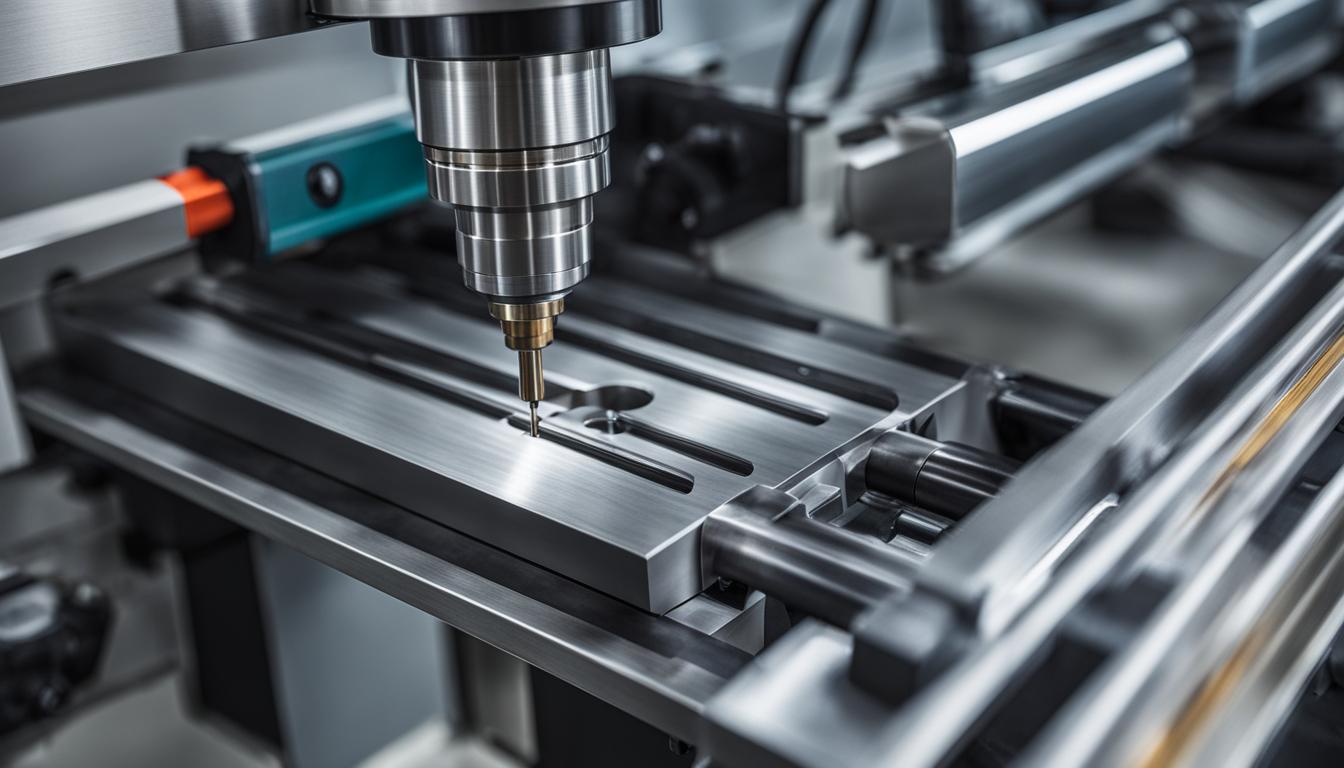
Computer numerical control (CNC) milling machines execute precise material removal operations across diverse industries. These sophisticated systems range from fundamental three-axis configurations to highly complex five-axis simultaneous platforms. Each machine type offers distinct advantages for specific part geometries and production volumes.
Foundational CNC Milling: 3-Axis Vertical Machining
Three-axis vertical milling remains a cornerstone of subtractive manufacturing, offering robust capabilities for a wide array of components. These machines operate along the X, Y, and Z linear axes, with the spindle typically oriented vertically. Workpieces are secured on a stationary table, and the cutting tool moves to perform operations like face milling, slotting, and drilling.
Modern 3-axis vertical machining centers (VMCs) are highly versatile, handling materials from aluminum to hardened steels. Standard positional tolerances for well-maintained VMCs typically fall within ±0.0005 to ±0.001 inch (±0.0127 to ±0.0254 mm) across their travel. Repeatability is often tighter, around ±0.0002 inch (±0.005 mm).
Typical feeds and speeds vary significantly based on material, tooling, and desired surface finish. For instance, milling 6061 aluminum with a 1/2-inch carbide end mill might involve spindle speeds of 8,000-12,000 RPM and feed rates of 40-80 inches per minute (IPM). Machining 4140 steel, however, would require lower speeds, perhaps 1,500-3,000 RPM, and feed rates of 10-25 IPM to manage heat and tool wear effectively.
Expanding Capabilities: 4-Axis Rotary Milling
| Milling Type | Axes | Typical Positional Tolerance | Common Spindle Orientation | Primary Applications |
|---|---|---|---|---|
| 3-Axis Vertical | 3 (X, Y, Z) | ±0.0005 – ±0.001 inch | Vertical | Flat parts, pockets, drilling |
| 4-Axis Rotary | 4 (X, Y, Z + A/B) | ±0.0005 – ±0.001 inch (linear) | Vertical or Horizontal | Cylindrical features, indexing |
| 5-Axis Simultaneous | 5 (X, Y, Z + 2 rotary) | ±0.0002 – ±0.0005 inch | Variable | Complex contours, impellers, molds |
| Horizontal Machining Center (HMC) | 3-5 (X, Y, Z + B/A/C) | ±0.0004 – ±0.0008 inch | Horizontal | High-volume production, large parts |
| High-Speed Micro Milling | 3-5 | ±0.00004 – ±0.0002 inch | Vertical | Micro-features, medical, optics |
Four-axis rotary milling introduces an additional rotational axis, typically designated as the ‘A’ axis, which allows the workpiece to rotate. This fourth axis is often integrated as a rotary table or indexing head, mounted on the machine’s primary table. This setup enables machining on multiple sides of a part without manual re-fixturing, significantly improving efficiency and accuracy for complex geometries.
The primary advantage of 4-axis machining lies in its ability to create features on cylindrical or prismatic parts that would be difficult or impossible with only three axes. Helical interpolation, cam profiles, and complex engraving around a part’s circumference are common applications. This reduces setup times and minimizes potential errors associated with multiple setups.
Positional tolerances for the rotary axis itself are critical, often specified in arc-seconds. A high-precision 4th axis can achieve indexing accuracies of ±5 to ±15 arc-seconds, translating to very tight linear tolerances at the workpiece’s periphery. This precision is crucial for maintaining feature alignment across different faces of a component.
Advanced Geometry: 5-Axis Simultaneous Machining
Five-axis simultaneous milling represents the pinnacle of CNC machining flexibility, incorporating two additional rotary axes alongside the standard three linear axes. These machines can orient the cutting tool and/or the workpiece in virtually any compound angle, allowing for continuous machining of highly complex, contoured surfaces in a single setup.
The two rotary axes can be configured in various ways, such as a trunnion table (A and C axes) or a swivel head (B and C axes). This simultaneous movement eliminates the need for multiple setups, reduces cumulative errors, and enables the use of shorter, more rigid cutting tools. Shorter tools minimize deflection and vibration, leading to superior surface finishes and extended tool life.
Industries like aerospace, medical, and mold making heavily rely on 5-axis capabilities for impellers, turbine blades, orthopedic implants, and intricate molds. Achieving tight tolerances, often ±0.0002 to ±0.0005 inch (±0.005 to ±0.0127 mm), is common, especially for critical features requiring high precision and excellent surface integrity.
Production Powerhouses: Horizontal Machining Centers (HMC)
Horizontal machining centers (HMCs) feature a horizontally oriented spindle, contrasting with the vertical orientation of VMCs. Workpieces are typically mounted on a pallet that can rotate (B-axis), allowing access to multiple sides of the part. This design is particularly advantageous for high-volume production and machining large, heavy components.
HMCs excel in chip evacuation due to gravity, which helps prevent chip re-cutting and improves tool life. Many HMCs incorporate automatic pallet changers, enabling continuous operation by allowing new parts to be loaded while another is being machined. This significantly boosts productivity and machine utilization.
These machines are often equipped with large tool magazines and robust structures, making them ideal for heavy material removal rates. Typical positional tolerances for HMCs are comparable to high-end VMCs, ranging from ±0.0004 to ±0.0008 inch (±0.010 to ±0.020 mm), with excellent thermal stability crucial for maintaining accuracy during long production runs.
Precision at Scale: High-Speed Micro Milling
High-speed micro milling focuses on machining features with dimensions in the micrometer range, often requiring specialized equipment and techniques. This process utilizes extremely small diameter cutting tools, typically below 1 mm, operating at very high spindle speeds, frequently exceeding 50,000 RPM and sometimes reaching 100,000 RPM or more.
Achieving micro-scale features demands exceptional machine rigidity, vibration damping, and precise motion control. Air-bearing spindles are common to minimize runout and maximize rotational accuracy. Specialized micro-grain carbide or diamond-coated tools are essential for maintaining sharp cutting edges and resisting wear at these scales.
Applications for high-speed micro milling include medical device components, micro-fluidic devices, optical molds, and intricate electronic parts. Tolerances in micro milling can be as tight as ±0.00004 to ±0.0002 inch (±1 to ±5 micrometers), necessitating environmental control and advanced metrology for verification.
Key considerations for micro milling operations:
- Tooling: Micro-end mills, ball mills, and drills from 0.001 to 1.0 mm diameter.
- Materials: Often specialized alloys, ceramics, and engineering plastics.
- Cooling: Air blast or minimal quantity lubrication (MQL) to prevent thermal shock and chip adhesion.
- Workholding: Vacuum chucks or specialized micro-fixtures to prevent part distortion.
The table below provides a comparative overview of key technical parameters across different CNC milling types.