
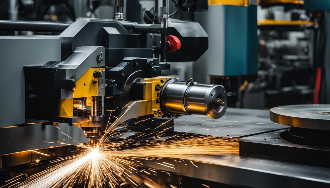
Computer Numerical Control, universally abbreviated as CNC, represents the automated operation of machine tools through a dedicated computer system. This technology has fundamentally transformed manufacturing by enabling precise, repeatable, and efficient production of complex parts. It is an evolution of earlier numerical control (NC) systems, which relied on less flexible data storage methods.
CNC machines integrate motorized tools and often maneuverable platforms, all guided by specific digital instructions. These instructions, typically in the form of G-code and M-code, are executed sequentially by the machine’s controller. While programs can be written manually, they are most frequently generated by Computer-Aided Design (CAD) and Computer-Aided Manufacturing (CAM) software.
From Punch Tape to Digital Control
The genesis of automated machining dates back to the 1940s, with the development of Numerical Control (NC) technology. John T. Parsons is widely credited with inventing the first NC machine in 1949, initially to produce helicopter blades using mathematically defined airfoil shapes. This groundbreaking system operated directly from punch cards, which dictated the machine’s movements.
Early NC machines, built in the 1940s and 1950s, were modifications of existing tools, augmented with motors that followed points fed into the system via punched tape or cards. The Massachusetts Institute of Technology (MIT) played a crucial role, demonstrating the first NC machine in 1952. Richard Kegg, in collaboration with MIT, later developed the Cincinnati Milacron Hydrotel, recognized as one of the first commercially available CNC milling machines.
The transition from NC to CNC occurred as computing costs declined, allowing for easier programming, real-time adjustments, and greater flexibility. By the late 1960s and 1970s, CNC machining began gaining widespread popularity, especially with the introduction of CAD systems in 1976, which streamlined the creation of 3D models and G-code generation.
G-Code: the Language of Automated Motion
| Nominal Dimension Range (mm) | Linear Tolerance (±mm) | Radius & Chamfer Tolerance (±mm) |
|---|---|---|
| 0.5 up to 3 | 0.10 | 0.20 |
| Over 3 up to 6 | 0.10 | 0.50 |
| Over 6 up to 30 | 0.20 | 1.00 |
| Over 30 up to 120 | 0.30 | 1.00 |
| Over 120 up to 400 | 0.50 | 2.00 |
G-code, often referred to as ‘geometric code’ or ‘preparatory code,’ serves as the fundamental programming language for CNC machines. It translates digital part designs into precise physical actions, instructing the machine on critical parameters such as tool movement, speed, and cutting operations.
Each line of G-code typically represents a single instruction, executed sequentially by the machine controller. Common G-code commands include G00 for rapid positioning (non-cutting moves), G01 for linear interpolation (controlled straight-line cutting), and G02/G03 for circular interpolation (clockwise/counter-clockwise arcs).
Beyond geometric commands, M-codes, or ‘miscellaneous codes,’ manage the machine’s auxiliary functions. These include actions like turning the spindle on or off, activating coolant flow, or initiating tool changes. G-codes and M-codes work in tandem to coordinate both tool movement and machine behavior, forming the backbone of CNC programming.
Digital Controller Functionality
The CNC controller acts as the ‘brain’ of the machine, interpreting G-code and coordinating all operational aspects. This hardware and software system calculates tool motion, manages feedback, and sends real-time commands to the machine’s axes, spindle, and other auxiliary systems.
Modern CNC controllers receive the machining program, typically G-code, and then perform interpolation calculations to coordinate multiple axes simultaneously. For instance, creating a diagonal line requires the X and Y axes to move together at precise relative speeds. Feedback systems, often utilizing encoders on the axes or motors, continuously monitor the actual position and report it back to the controller, ensuring accuracy.
CNC machines typically employ a right-handed Cartesian coordinate system (X, Y, Z axes) to define tool and workpiece positions. The machine coordinate system establishes the machine’s fixed home position, while the Work Coordinate System (WCS) allows programmers to define a convenient zero point on the workpiece itself, often using G54-G59 codes. This flexibility is crucial for multi-part setups and complex geometries.
Industrial Manufacturing Role and Modern Practices
CNC machining has revolutionized industrial manufacturing due to its unparalleled precision, repeatability, and efficiency. It enables the consistent production of parts with tight tolerances, often as fine as 0.0001 inches, which is critical for industries like aerospace, automotive, and medical devices.
The advantages extend to faster production speeds, reduced labor costs over time, and minimal material waste through optimized toolpaths. CNC systems can operate continuously with minimal human intervention, supporting high-volume manufacturing and rapid prototyping.
Current trends in CNC manufacturing for 2026 emphasize deeper automation, integration of artificial intelligence (AI), and advanced connectivity. AI is increasingly used for practical applications such as tool wear detection, predictive maintenance, and optimizing cutting parameters in real-time. Hybrid manufacturing, blending subtractive CNC with additive processes, is also gaining momentum for complex near-net-shape parts.
Standard tolerances in CNC machining are often governed by international standards like ISO 2768. This standard provides general tolerances for linear and angular dimensions when specific tolerances are not explicitly indicated on a drawing. ISO 2768-1 categorizes tolerances into fine (f), medium (m), coarse (c), and very coarse (v), with ‘medium’ being the industry standard for most parts. For precision fits, ISO 286 is used, defining specific shaft and hole deviations.
Selecting appropriate feeds and speeds is critical for optimizing tool life, surface finish, and material removal rates. These parameters depend heavily on the workpiece material, cutting tool material and geometry, and machine rigidity. For instance, machining 304 stainless steel with carbide end mills typically involves cutting speeds of 200–250 SFM (60–75 m/min) and feed per tooth between 0.002–0.006 in/tooth (0.05–0.15 mm/tooth).
Conversely, aluminum 6061 allows for much higher cutting speeds, often in the range of 800–1,000 SFM. Adjustments are constantly made to prevent issues like built-up edge, work hardening, or poor surface finish. Modern CAM software and AI-driven systems assist in calculating and dynamically adjusting these parameters for optimal performance.