
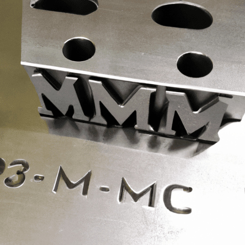
Manufacturing with metal encompasses a diverse array of processes, each offering unique advantages for specific applications. From shaping raw material through extreme force to precisely removing material with automated tools, the capabilities of metalworking are fundamental to nearly every industrial sector.
Understanding the technical nuances of these methods, including their inherent tolerances, material suitability, and operational parameters, is crucial for engineers and machinists aiming to produce high-quality, functional components.
Casting and Forging
Casting involves pouring molten metal into a mold cavity, allowing it to solidify into a desired shape. This process offers significant design flexibility, enabling the creation of complex geometries, intricate details, and internal cavities that would be challenging or impossible to achieve with other methods.
Common casting alloys include various irons, steels, aluminum, and brass, each selected for specific mechanical properties like ductility, corrosion resistance, or temperature tolerance. While sand casting is versatile for large, complex parts, precision methods like die casting and investment casting yield tighter tolerances and smoother surface finishes.
Forging, in contrast, shapes solid metal using localized compressive forces, such as hammering, pressing, or rolling, often performed on heated metals. This mechanical deformation refines the metal’s grain structure, aligning it along the part’s contours, which significantly enhances mechanical properties like tensile strength, fatigue resistance, and impact toughness.
Forged components generally exhibit superior strength and durability compared to cast parts of the same alloy composition due to this refined grain flow and reduced internal porosity. Open-die forging is suitable for large, simple shapes, while closed-die (impression) forging is used for more defined geometries, and upset forging increases the diameter of a bar section.
Typical dimensional tolerances for sand castings, as per ISO 8062, can range from CT8 to CT12, with machine-produced sand molds achieving CT8. Investment casting, a precision method, can achieve tighter tolerances, often around ±0.010 inches for the first inch and ±0.004 inches for each subsequent inch.
Surface finishes for general metal casting design applications can range from Ra 12.5 µm to 25 µm, while automotive castings typically require Ra 3.2 to 12.5 µm. Die casting can achieve a much smoother surface finish, with Ra values of 0.8-3.2 µm.
CNC Machining
Computer Numerical Control (CNC) machining is a subtractive manufacturing process that uses programmed computer commands to control machine tools, precisely removing material from a workpiece. This method is renowned for its high precision, repeatability, and ability to produce intricate designs with tight dimensional tolerances.
Modern CNC machines, including mills, lathes, and multi-axis systems, can work with a vast array of materials, from aluminum and steel to titanium and engineering plastics. The accuracy of CNC machining allows for typical dimensional tolerances ranging from ±0.025 mm to ±0.125 mm for standard milling operations, and even tighter for turning.
Tooling choices are critical in CNC machining, with materials like High-Speed Steel (HSS) and cemented carbide being prevalent. HSS tools are tougher and less brittle, suitable for lower-speed operations and interrupted cuts, while carbide tools offer superior hardness and heat resistance, ideal for high-speed machining of harder materials.
Coatings such as Titanium Nitride (TiN), Titanium Carbo-Nitride (TiCN), and Aluminum Titanium Nitride (Al-TiN) further enhance tool life and performance by increasing hardness, lubricity, and heat resistance. Polycrystalline Diamond (PCD) tools excel on non-ferrous materials like aluminum and copper, while Cubic Boron Nitride (CBN) is preferred for finishing hardened steels.
Optimizing feeds and speeds is paramount for efficient CNC machining, balancing material removal rates, tool life, and surface finish. For 6061 aluminum, carbide tools typically operate at cutting speeds between 1000 and 4000 surface feet per minute (SFM), with chip loads ranging from 0.002 to 0.005 inches per tooth for milling.
Insufficient chip load can lead to ‘built-up edge’ and smearing, while excessive chip load can cause work hardening or tool deflection. For 4140 steel, a common alloy, cutting speeds are significantly lower, often in the range of 200-600 SFM for carbide, with chip loads adjusted based on hardness and tool geometry.
Coolant or mist lubrication is often essential, especially for aluminum, to prevent chip welding and improve surface finish.
Sheet Metal Fabrication
Sheet metal fabrication involves transforming flat metal sheets into desired shapes through processes like cutting, bending, and forming. This method is widely used for enclosures, brackets, chassis, and structural components across various industries.
Common materials include steel (mild, stainless), aluminum, and copper alloys, selected based on strength, corrosion resistance, and formability. The choice of cutting method significantly impacts edge quality and achievable tolerances.
Laser cutting offers high precision and narrow kerf widths, with typical positional tolerances of ±0.1 mm and cut-edge perpendicularity within 0.1-0.2 mm for material thicknesses up to 10 mm. Plasma cutting is faster for thicker materials but generally yields wider kerfs and larger heat-affected zones, resulting in tolerances of ±0.5 mm to ±1.5 mm.
Waterjet cutting provides excellent edge quality without heat distortion, achieving tolerances of ±0.1 mm to ±0.25 mm, though at slower speeds. Bending operations, often performed on press brakes, typically hold angular tolerances of ±0.5 to ±1.0 degrees, with dimensional tolerances on bent features influenced by material thickness, bend radius, and machine calibration.
Forming processes, such as stamping, deep drawing, and roll forming, create complex three-dimensional shapes from sheet metal. Stamping uses dies to cut and form parts rapidly, suitable for high-volume production, while deep drawing creates hollow, cup-shaped parts.
Roll forming continuously bends metal strips into desired cross-sections. These processes require careful consideration of material springback, which is the tendency of the metal to return to its original shape after bending, necessitating over-bending to achieve the target angle.
Tooling for sheet metal fabrication is typically made from hardened tool steels, often with surface treatments to reduce wear and galling.
Welding and Joining
Welding is a fundamental process for permanently joining metal components by melting the workpieces and often adding a filler material. This creates a strong, monolithic bond essential for structural integrity in applications ranging from automotive frames to pressure vessels.
Various welding techniques exist, each suited for different materials, thicknesses, and joint configurations.
Gas Metal Arc Welding (GMAW), commonly known as MIG welding, uses a continuously fed wire electrode and a shielding gas. It is highly versatile, fast, and suitable for a wide range of materials, including mild steel, stainless steel, and aluminum.
Typical parameters for MIG welding mild steel involve wire feed speeds of 150-400 inches per minute and voltage settings of 18-28V, depending on wire diameter and material thickness. Gas Tungsten Arc Welding (GTAW), or TIG welding, utilizes a non-consumable tungsten electrode and an inert shielding gas, often 100% argon.
TIG welding provides superior control, producing high-quality, precise welds with excellent aesthetic appeal, making it ideal for stainless steel, aluminum, and exotic alloys. For stainless steel, TIG amperage typically ranges from 60-80 amps for 1/16′ (1.6mm) thickness, increasing to 180-250 amps for 1/4′ (6.4mm) material, with a consistent arc length of approximately 1/8 inch (3mm).
Achieving sound welds requires meticulous preparation, including thorough cleaning of base materials to remove contaminants like dirt, grease, and oxides. Proper joint design, such as butt, lap, corner, or T-joints, is crucial for distributing stress effectively and ensuring adequate penetration.
Welding distortion, caused by uneven heating and cooling, is a common challenge that can be mitigated through techniques like proper clamping, pre-setting, and controlled cooling rates. Modern joining techniques also include brazing, soldering, and adhesive bonding, which offer alternatives for specific applications where lower heat input or dissimilar material joining is required.
Heat Treating and Hardening
Heat treatment processes are metallurgical techniques that alter the physical and mechanical properties of metals through controlled heating and cooling cycles. These processes are vital for enhancing characteristics such as hardness, strength, ductility, toughness, wear resistance, and fatigue strength, tailoring materials for specific demanding conditions.
Common heat treatment methods for steel include annealing, normalizing, hardening, and tempering. Annealing involves heating the metal to a specific temperature and then slowly cooling it, typically within the furnace, to relieve internal stresses, soften the metal, and improve ductility and machinability.
Normalizing heats the steel above its critical temperature and then cools it in air, resulting in a finer grain structure and improved mechanical properties compared to annealed steel. Hardening involves heating the steel to its austenitizing temperature, holding it, and then rapidly cooling it (quenching) in media like water, oil, or polymer solutions to form a hard, martensitic structure.
This rapid cooling locks in a hardened microstructure, significantly increasing hardness and strength.
Tempering is almost always performed after hardening to reduce the brittleness associated with martensite while retaining a significant portion of the hardness. This involves reheating the quenched steel to a lower temperature, allowing for some atomic rearrangement and stress relief.
Surface hardening techniques, also known as case hardening, create a hard, wear-resistant outer layer while maintaining a tougher, more ductile core. Methods like carburizing introduce carbon into the surface, nitriding introduces nitrogen, and induction or flame hardening selectively heat and quench the surface.
These processes are critical for components requiring high surface wear resistance and impact absorption, such as gears, bearings, and cutting tools.
| Process | Typical Dimensional Tolerance (mm) | Typical Surface Finish (Ra µm) |
|---|---|---|
| Sand Casting | ±0.8 to ±3.0 | 12.5 to 25 |
| Die Casting | ±0.05 to ±0.2 | 0.8 to 3.2 |
| Open-Die Forging | ±1.0 to ±5.0 | 6.3 to 12.5 |
| Closed-Die Forging | ±0.2 to ±1.0 | 3.2 to 6.3 |
| CNC Milling (Standard) | ±0.025 to ±0.125 | 0.8 to 3.2 |
| CNC Turning (Standard) | ±0.01 to ±0.05 | 0.4 to 1.6 |
| Laser Cutting (Sheet Metal) | ±0.1 to ±0.2 | 1.6 to 6.3 |
| Waterjet Cutting (Sheet Metal) | ±0.1 to ±0.25 | 3.2 to 6.3 |