
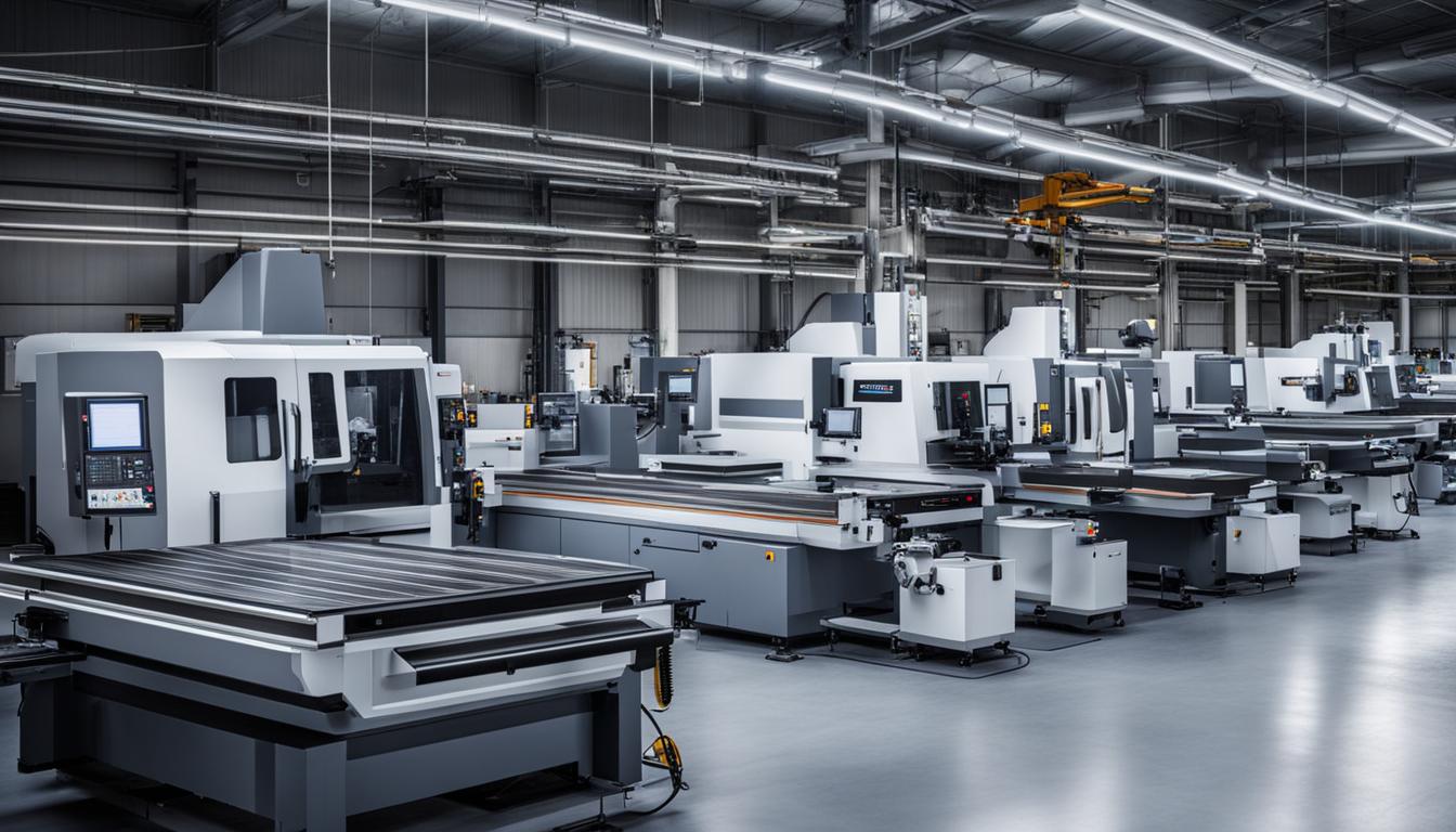
The Z-axis on a Computer Numerical Control (CNC) machine fundamentally dictates the vertical movement of the cutting tool or workpiece, establishing the crucial dimension for depth control. This axis is integral to all subtractive manufacturing processes, from milling and drilling to turning operations. Its precise orientation and programmed movements are critical for achieving accurate part geometries and maintaining operational safety.
Understanding the Z-Axis in CNC Coordinate Systems
CNC machining relies on a Cartesian coordinate system, which employs X, Y, and Z axes to define movement in three-dimensional space. The X-axis typically controls horizontal left-to-right motion, while the Y-axis manages horizontal front-to-back movement. The Z-axis, in contrast, governs the vertical dimension, enabling the tool to move up and down relative to the workpiece.
International standards, such as ISO 841 and ANSI/ASME B5.54, standardize these axis conventions across various machine tools. These standards stipulate that the Z-axis is always aligned with the machine’s principal spindle. This universal rule ensures consistent programming and operation, regardless of the specific machine configuration.
The right-hand rule is a common method for determining the positive directions of the linear axes. When the middle finger points in the positive Z-axis direction, the thumb indicates the positive X-axis, and the index finger points to the positive Y-axis. This convention is vital for correctly interpreting machine movements and programming toolpaths.
Spindle Stroke and Z-Axis Orientation
| Tolerance Type | Typical Range (Inches) | Typical Range (Millimeters) | Application |
|---|---|---|---|
| Standard Machining | ±0.005″ | ±0.127 mm | General-purpose parts, prototypes, non-critical features |
| Precision Machining | ±0.001″ to ±0.002″ | ±0.025 mm to ±0.051 mm | Tight fits, critical features, performance-dependent accuracy |
| High Precision (Specialized) | ±0.0001″ to ±0.0005″ | ±0.0025 mm to ±0.0127 mm | Medical devices, aerospace, grinding, wire EDM |
The Z-axis’s physical orientation on a CNC machine is directly tied to the spindle’s movement. On vertical machining centers (VMCs), the spindle is positioned vertically, and consequently, the Z-axis controls the direct up and down motion of the machine head. This setup is prevalent for operations requiring the cutting tool to approach the workpiece from above, such as drilling and milling.
Horizontal CNC machines present a different orientation, with the spindle mounted parallel to the floor. Here, the Z-axis still dictates the spindle’s movement toward or away from the workpiece face, but this motion occurs in and out (back and forth) rather than up and down. This configuration can be advantageous for chip evacuation, as gravity helps clear debris from the cutting zone.
CNC lathes operate with a distinct dynamic where the workpiece rotates in the chuck. On these machines, the Z-axis runs horizontally, parallel to the spindle’s rotation, controlling the tool carriage’s movement along the length of the spinning part. This longitudinal movement is essential for turning, facing, and threading operations.
Positive and Negative Z Movements
A fundamental principle in CNC programming defines the positive and negative directions of the Z-axis. Moving the cutting tool away from the workpiece is universally considered the positive Z direction (+Z). Conversely, moving the tool toward the material to initiate a cut is defined as the negative Z direction (-Z).
This convention is critical for safe and efficient machining. A positive Z movement typically retracts the spindle and tool upward, clearing clamps, fixtures, or the workpiece itself before repositioning. This action prevents accidental collisions and facilitates tool changes.
Conversely, a negative Z movement plunges the cutting tool downward into the material, establishing the desired cutting depth. Understanding this directional logic is paramount for preventing costly machine crashes and ensuring accurate toolpaths, especially when setting the Z-axis zero point at the top surface of the raw material.
Depth of Cut Direction and Control
Depth of cut (DOC) is a critical machining parameter that refers to the thickness of material removed in a single pass of a cutting tool. In milling, this is often referred to as axial depth of cut (ADOC), which measures how far the tool plunges along its own axis into the material. This directly corresponds to negative Z-axis movement.
The chosen depth of cut significantly impacts tool life, cycle time, surface finish, and part accuracy. An overly aggressive depth can lead to increased cutting forces, heat generation, and tool deflection, potentially causing tool breakage or poor surface quality. Conversely, a shallow depth of cut may prolong cycle times unnecessarily.
For optimal results, the depth of cut must be carefully selected based on factors such as tool geometry, material hardness, machine rigidity, and whether the operation is roughing or finishing. Roughing passes typically employ larger depths of cut to remove bulk material quickly, while finishing passes use shallower depths to achieve tight tolerances and superior surface finishes.
Precision and Performance: Tolerances, Feeds, and Speeds
Achieving precise Z-axis control is fundamental to meeting stringent dimensional tolerances in CNC machining. Standard tolerances for most metals typically fall within ±0.005 inches (±0.127 mm). However, precision machining operations can reliably hold much tighter tolerances, often in the range of ±0.001 inches (±0.025 mm) or even tighter for critical applications.
These tighter tolerances demand slower cutting speeds, high-precision tooling, and often temperature-controlled environments to minimize thermal expansion effects. The Z-axis’s ability to maintain consistent depth throughout a cut directly influences the final part’s adherence to these specified limits.
The plunge rate, which is the speed at which the tool moves downwards along the Z-axis, is a critical feed and speed parameter. Unlike horizontal feed rates, plunge rates are generally much lower, typically ranging from 25% to 50% of the cutting feed rate. This reduction is necessary because end mills are designed for efficient lateral cutting, not vertical drilling, and plunging directly can generate excessive heat and stress on the tool.
Proper plunge rates, often combined with ramping or helical entry strategies, help prevent tool damage and ensure smooth material entry. For instance, a 4-flute end mill is generally suboptimal for plunging into aluminum, where a 2-flute end mill is preferred for better chip evacuation and reduced clogging risk. Always verify that the end mill is center-cutting before any direct plunge operation.