
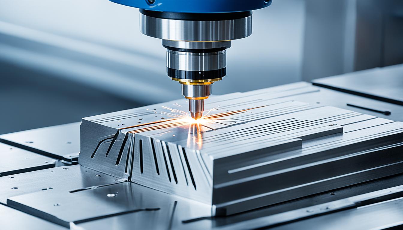
Manual Data Input (MDI) mode on a Computer Numerical Control (CNC) machine allows operators to execute individual G-code or M-code commands directly from the control panel. This interactive feature provides immediate control over machine functions, bypassing the need for a complete, stored program.
MDI is particularly useful for quick, one-off tasks, machine setup, and troubleshooting, offering a flexible interface for direct operator intervention. It enables machinists to perform actions that might not be possible in the machine’s manual jog mode, such as activating an automatic tool changer.
Manual Data Input Mode Fundamentals
MDI mode functions as an interactive dialogue between the operator and the CNC machine. Operators access this mode via a dedicated button on the control panel, which typically opens a ‘scratch pad’ or input area on the display screen.
Commands, including G-codes for geometric movements and M-codes for miscellaneous functions, are typed into this area. Upon pressing ‘Cycle Start’ or a similar execution button, the CNC controller reads and immediately executes the entered block or short sequence of blocks.
Unlike full programs stored in memory, MDI commands are generally executed once and then cleared from the input area, making them ideal for temporary operations. This ‘use once and discard’ nature prevents MDI commands from consuming valuable memory space on the controller.
The ability to directly input and execute code provides a powerful means for operators to interact with the machine in real-time, facilitating tasks that require precise, immediate control without extensive programming. This direct control enhances operational efficiency and reduces setup time.
Single-Line G-Code Execution
| Parameter | Standard Tolerance (mm) | Standard Tolerance (inches) | Precision Tolerance (mm) | Precision Tolerance (inches) |
|---|---|---|---|---|
| Linear Dimensions | ±0.125 | ±0.005 | ±0.025 to ±0.012 | ±0.001 to ±0.0005 |
| Angular Dimensions | ±0.5° | — | ±0.25° | — |
| Milling (Typical) | ±0.025 | ±0.001 | Up to ±0.01 | Up to ±0.0004 |
Executing single-line G-code commands in MDI mode is a core functionality for CNC operators. This allows for precise, controlled movements and actions without the complexity of a full program. For instance, a command like ‘G00 X100.0 Y50.0’ would rapidly position the tool to X100.0 and Y50.0.
Each command entered in MDI is processed individually, and the machine typically stops after its execution, awaiting the next input. This block-by-block execution is crucial for verifying program logic or diagnosing issues in a controlled manner.
Operators can use single-line commands for various purposes, including moving axes to specific coordinates, setting work offsets, or initiating tool changes. The simplicity and immediacy of MDI make it an indispensable tool for quick adjustments and checks on the shop floor.
Some advanced controllers offer a ‘step-by-step’ option within MDI, where each instruction is executed and then paused, requiring another ‘Cycle Start’ press to proceed. This provides an even finer level of control for complex or critical operations.
Setup Tool Positioning
MDI mode is extensively used for critical setup operations, particularly for tool positioning and offset adjustments. Before a production run, operators often use MDI to call a specific tool into the spindle, set its length offset, or define workpiece coordinate systems.
For example, an operator might enter ‘T01 M06’ to command a tool change to tool number 1. Following this, they can use MDI to move the tool to a known reference point, touch off the workpiece, and then input the measured values into the tool offset registers.
Tool length offsets (H-offsets) and cutter compensation (D-offsets) are vital for ensuring accurate machining. MDI allows for the manual input and verification of these values, ensuring the machine understands the physical dimensions of each tool relative to the workpiece.
Setting work coordinate system (WCS) origins, such as G54, is another common MDI application. Operators can jog the tool to a desired origin point on the workpiece and then use an MDI command, often in conjunction with a ‘Work Offset Measure’ function, to establish the part zero.
Spindle Test Commands
Testing spindle functionality is a frequent MDI application, ensuring the spindle operates correctly before machining begins. Operators can issue specific M-codes to control spindle rotation and G-codes to set its speed.
Common M-codes for spindle control include M03 for clockwise rotation, M04 for counter-clockwise rotation, and M05 to stop the spindle. These are typically paired with an ‘S’ word to define the desired Revolutions Per Minute (RPM).
For instance, entering ‘S1500 M03’ in MDI mode will start the spindle rotating clockwise at 1500 RPM. This allows for quick checks of spindle direction, speed, and overall health without needing a full program.
These commands are essential for tasks like checking tool runout, cleaning the spindle taper, or simply verifying that the spindle motor and drive are functioning as expected. It’s a fundamental step in machine preparation and maintenance.
Controller Manual Overrides
CNC controllers incorporate manual override functions that allow operators to adjust machining parameters in real-time, even during MDI execution or automatic program runs. These overrides provide critical flexibility and safety.
Common overrides include feed rate, spindle speed, and rapid traverse. Operators can increase or decrease these parameters using dedicated buttons or dials on the control panel, typically ranging from 0% to 150% or more of the programmed value.
While MDI commands themselves define specific speeds and feeds, the manual overrides allow for immediate, temporary adjustments. For example, if a tool exhibits chatter during an MDI-initiated cut, the operator can instantly reduce the feed rate override to stabilize the process.
This capability is invaluable for optimizing cutting conditions, extending tool life, and preventing damage to the workpiece or machine, especially when running new tools or materials. It bridges the gap between programmed instructions and real-world machining dynamics.
Standard CNC Machining Tolerances
Achieving precise dimensions is paramount in CNC machining, and standard tolerances guide the acceptable deviation from nominal values. For most linear dimensions in general CNC machining, a tolerance of ±0.125 mm (±0.005 inches) is commonly applied.
Precision CNC machining can achieve tighter tolerances, often ranging from ±0.025 mm (±0.001 inches) down to ±0.012 mm (±0.0005 inches) for critical features. Some high-precision processes like grinding or wire EDM can even reach ±0.0025 mm (±0.0001 inches) under controlled conditions.
These tolerances vary based on the specific machining process, material, and machine capabilities. For instance, CNC milling typically holds around ±0.025 mm, while turning operations can achieve similar or tighter results for cylindrical features.
Engineers must carefully consider the functional requirements of a part when specifying tolerances. Over-specifying tight tolerances can significantly increase manufacturing costs and lead times due to slower machining speeds and additional quality checks.