
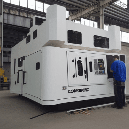
Computer Numerical Control, widely known as CNC, represents the automated control of machine tools through a computer system. This technology forms the backbone of modern precision production, enabling machines to cut, carve, and shape various materials with exceptional accuracy. It has fundamentally transformed manufacturing processes, moving away from manual operation towards digital instruction.
The core concept of CNC involves pre-programmed computer code guiding machine tool movements, ensuring consistent and precise part creation every time. This system evolved from earlier numerical control (NC) methods, which relied on data storage media like punched cards, offering easier programming and real-time adjustments as computing costs decreased.
Understanding Computer Numerical Control
CNC technology integrates several critical components to function effectively. A machine control unit (MCU) acts as the ‘brain,’ interpreting the coded instructions. Drive systems, often comprising servo or stepper motors, translate these commands into physical motion along multiple axes.
Feedback systems, such as encoders, continuously monitor the actual position and speed of the machine’s axes, reporting back to the MCU to ensure accuracy and make necessary corrections. This closed-loop control is vital for maintaining tight tolerances during complex machining operations. The machine tool itself, whether a mill, lathe, or router, performs the material removal based on these precise digital instructions.
Compared to conventional manual control, CNC offers significant advantages, including automated movement of machine tools and the ability to create an infinite number of identical parts from a single program. This repeatability drastically reduces variations between manufactured components, enhancing overall product quality and reliability.
Automated Milling and Turning Operations
| Characteristic | CNC Milling | CNC Turning |
|---|---|---|
| Workpiece State | Stationary | Rotating |
| Tool Motion | Rotary cutting tool moves | Stationary tool moves linearly |
| Primary Geometry | Complex 3D shapes, flat surfaces | Cylindrical, conical, spherical |
| Typical Axes | 3, 4, 5-axis | 2-axis (basic), C-axis, Y-axis (advanced) |
CNC milling is a foundational process in modern machine shops, utilizing rotating cutting tools to remove material from a stationary workpiece. These machines typically feature multiple linear axes, commonly 3-axis, 4-axis, and 5-axis configurations, allowing for the creation of intricate geometries and complex contoured surfaces.
CNC turning, conversely, involves a workpiece rotating at high speeds while a stationary cutting tool removes material to form precise, symmetrical parts. This method is particularly effective for producing cylindrical components such as shafts, bushings, and threaded elements with smooth finishes and tight tolerances.
The integration of turning and milling capabilities into single ‘mill-turn’ machines offers substantial benefits. These combined operations eliminate the need for transferring workpieces between different machines, significantly reducing setup times and enhancing overall efficiency. Mill-turn centers also improve precision by completing multiple operations in one setup, minimizing potential errors from re-fixturing.
Achieving Precision in CNC Machining
Precision is a non-negotiable requirement in contemporary manufacturing, especially for critical components in aerospace, medical devices, and automotive industries. CNC machining delivers the high accuracy and stable quality demanded by these applications, ensuring parts function correctly and fit together perfectly.
Standard CNC machining tolerances typically range from ±0.05 mm to ±0.13 mm (±0.002″ to ±0.005″) for most milling and turning operations. Achieving tighter tolerances, such as ±0.025 mm (±0.001″) or even ±0.013 mm (±0.0005″), is considered high precision and often requires specialized equipment, controlled environments, and advanced measurement capabilities.
Material properties significantly influence achievable tolerances. Aluminum alloys, for instance, can achieve ±0.05 mm, while stainless steel typically holds ±0.10 mm, and engineering plastics may require wider tolerances of ±0.15 mm to ±0.25 mm. Proper metrology and quality control systems are essential to verify these precise dimensions throughout the production cycle.
Optimizing feeds and speeds is crucial for achieving desired precision and extending tool life. For aluminum, typical milling parameters might involve 8,000–12,000 RPM with 40–80 IPM feed, while turning roughing operations might use 0.25–0.5 mm/rev feed. These parameters must be carefully matched to material density, tool geometry, and machine rigidity to prevent issues like burning, chatter, or premature tool wear.
Digital Workflow and Manufacturing Integration
The digital manufacturing workflow begins with Computer-Aided Design (CAD) software, where engineers create detailed 3D models of parts. These designs are then translated into machine-readable instructions using Computer-Aided Manufacturing (CAM) software, which generates toolpaths and cutting parameters.
Data flows seamlessly from CAD to CAM and then to the CNC machine controller, forming a cohesive digital pipeline. Modern workflows increasingly incorporate simulation and virtual commissioning, allowing engineers to visualize toolpaths, detect potential collisions, and validate kinematics before any material is cut. This proactive approach significantly reduces setup errors and lead times.
The year 2026 sees digital twins maturing into comprehensive ecosystems that mirror the entire machining process, integrating design, process engineering, machining, and inspection into continuously updated models. Artificial intelligence (AI) is also becoming integral, using real-time sensor feedback to automatically adjust feeds, speeds, and toolpaths, thereby improving surface quality and reducing tool wear.
Executing Blueprints with G-Code
Engineering blueprints, also known as technical drawings, remain fundamental documents in CNC manufacturing, providing standardized information on dimensions, tolerances, hole features, and surface finishes. Machinists must accurately interpret these symbols and specifications to translate design intent into physical parts.
G-code, or ‘Geometric Code,’ is the primary programming language that instructs CNC machines on specific actions, such as where to move, how fast to move, and what path to follow. M-codes, or ‘Miscellaneous Codes,’ control auxiliary functions like spindle start/stop, tool changes, and coolant activation.
CAM software generates these G-code and M-code programs, which are then post-processed to be compatible with the specific CNC machine controller. This machine-specific code ensures the machine executes the design precisely, turning digital instructions into physical material removal.
- G00: Rapid positioning (non-cutting move at maximum speed)
- G01: Linear interpolation (straight line move at a specified feed rate)
- G02: Circular interpolation clockwise (arc move in a clockwise direction)
- G03: Circular interpolation counterclockwise (arc move in a counterclockwise direction)
- G04: Dwell (pause in program execution for a specified duration)
- G20/G21: Units selection (inch or millimeter system)
- G40/G41/G42: Cutter compensation (cancel, left, or right compensation)
- G90/G91: Positioning (absolute or incremental programming)