
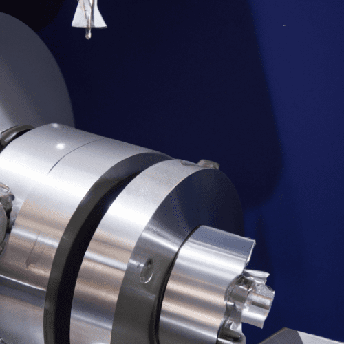
Computer Numerical Control (CNC) turning is a subtractive manufacturing process that precisely shapes cylindrical parts by rotating a workpiece against a stationary cutting tool. This method is fundamental across industries, producing components from simple pins to complex aerospace parts with exceptional accuracy and repeatability.
Modern CNC turning centers, often equipped with multi-axis capabilities and live tooling, extend beyond basic turning to perform drilling, milling, and threading operations without repositioning the workpiece. This integration significantly enhances efficiency and part complexity.
The Lathe Setup Operator’s Critical Role
Before any material is cut, a CNC lathe setup operator performs a thorough machine inspection, verifying mechanical components like the spindle, tool turret, and axes for wear or damage. Ensuring machine guards are in place and all safety protocols are followed is paramount.
Selecting the correct workholding device, such as a chuck or collet, is essential for securing the workpiece accurately and rigidly. Operators then load the appropriate turning, boring, or drilling tools into the turret, ensuring they are sharp and in good condition for the specific job.
Setting tool offsets, which account for the physical dimensions of each tool, is a critical step in the CNC control system. This calibration ensures the machine precisely positions the cutting edges relative to the workpiece, followed by loading the CNC program (G-code) into the controller.
Crafting Cylindrical Parts with Precision
| Parameter | Description | Typical Range/Value |
|---|---|---|
| Standard Tolerance (ISO 2768-1 m) | General purpose machining tolerance | ±0.005 in (0.13 mm) |
| Precision Tolerance (ISO 2768-1 f) | For tighter accuracy requirements | ±0.002 in (0.051 mm) |
| Aluminum Cutting Speed (SFM) | Surface Feet per Minute for Aluminum | 600-800 SFM |
| Steel Cutting Speed (SFM) | Surface Feet per Minute for Steel | 100-300 SFM |
| Stainless Steel Cutting Speed (SFM) | Surface Feet per Minute for Stainless Steel | 50-150 SFM |
| Roughing Feed Rate (Turning) | Aggressive material removal | 0.25–0.5 mm/rev |
| Finishing Feed Rate (Turning) | Achieving desired surface finish | 0.05–0.15 mm/rev |
CNC turning excels at producing parts with cylindrical symmetry, including shafts, bushings, pins, and threaded components. The process involves the workpiece rotating at high speed while the cutting tool removes material to achieve the desired shape and size.
Optimizing feeds and speeds is crucial for efficient material removal, tool life, and surface finish. Cutting speed, measured in surface feet per minute (SFM) or meters per minute, depends on the material type and tool material. Feed rate, typically expressed in inches or millimeters per revolution, dictates how quickly the tool advances into the material.
For roughing operations, higher feed rates (0.25–0.5 mm/rev) and deeper cuts are employed to remove material rapidly. Finishing passes utilize lower feed rates (0.05–0.15 mm/rev) to achieve superior surface finish and meet tight dimensional tolerances.
Mastering Threading Operations
Threading on a CNC lathe involves cutting helical grooves into a cylindrical surface, creating internal or external threads for fasteners or connections. This is typically achieved using single-point threading inserts, where the insert’s shape and size must match the finished thread profile.
CNC machines utilize specialized G-code cycles, such as the G76 threading cycle, to automate this complex process. Operators program parameters including the thread pitch, total cutting depth, and the depth of cut for the initial and final passes.
Adjusting the infeed method and the number of passes is vital for optimizing tool life and thread quality. For multi-start threads, the lead increases relative to the pitch by a multiple equal to the number of starts, requiring careful shim selection to ensure the correct inclination angle.
Precision Measurement for Quality Assurance
Precision machining demands accurate measurement to ensure parts meet exact specifications and function correctly. Machinists must develop confidence through consistent verification, transforming raw material into components with predictable outcomes.
Essential handheld tools include calipers for quick readings and versatility, and micrometers for achieving sub-thousandth accuracy on outside dimensions. Dial indicators are indispensable for measuring small movements and ensuring machine setup alignment.
Advanced inspection often involves bore gauges, pin gauges, and Coordinate Measuring Machines (CMMs) for verifying complex 3D relationships and internal features. Interpreting engineering drawings and understanding ISO tolerance standards like ISO 2768-1 and ISO 286 are fundamental skills for a precision measuring expert.
The Machine Control Technician’s Expertise
A machine control technician is responsible for programming, operating, and monitoring the CNC system that directs the lathe’s movements. This involves loading and adjusting G-code programs, which are the instructions dictating tool paths, speeds, and feeds.
During production, the technician continuously monitors machine performance, detecting issues such as tool wear, misalignment, or material defects. They make real-time adjustments to parameters like cutting depth and feed rates to maintain accuracy and efficiency.
Modern CNC control systems, such as those from FANUC, offer advanced capabilities for high-speed, high-accuracy performance across multi-axis turning centers. These systems provide flexible screens, multi-axis control, and features for fine surface machining, simplifying operation and programming.