
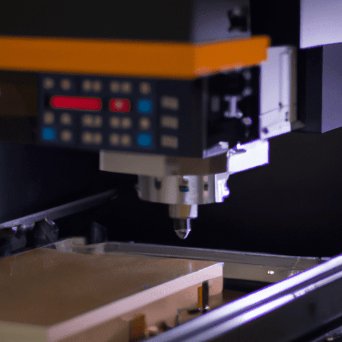
A milling machine is a fundamental subtractive manufacturing tool that precisely removes material from a workpiece using rotating multi-point cutting tools. This process shapes raw stock into desired geometries, ranging from simple flats to intricate 3D contours. Its versatility makes it indispensable across industries, from aerospace to medical device manufacturing.
Milling is a machining process where rotary cutters remove material by advancing the workpiece into the cutter. This can involve varying directions on one or several axes, adjusting cutter head speed, and controlling pressure.
The Core Principle of Subtractive Machining
Subtractive manufacturing fundamentally involves removing material to achieve a final part shape. Unlike additive processes, which build up material layer by layer, milling machines start with a solid block and systematically cut away excess. This method is highly effective for producing parts with tight tolerances and superior surface finishes.
The material removal process relies on the mechanical interaction between a rotating cutting tool and a stationary or moving workpiece. Chips are generated as the tool’s cutting edges shear material, dissipating heat and carrying away waste. Effective chip evacuation is critical for maintaining tool life and surface quality.
Modern milling operations often employ Computer Numerical Control (CNC) systems. These systems interpret digital design files (CAD/CAM) into precise machine movements, automating complex machining paths. This automation significantly enhances repeatability and accuracy, crucial for high-volume production and intricate component fabrication.
Spindle Drive Systems and Power Delivery
| Feature Type | Standard Tolerance (mm) | Standard Tolerance (inches) |
|---|---|---|
| Linear Dimensions | ±0.025 to ±0.125 | ±0.001 to ±0.005 |
| Hole Diameter | ±0.025 to ±0.075 | ±0.001 to ±0.003 |
| Flatness | 0.05 to 0.15 | 0.002 to 0.006 |
| Perpendicularity | 0.05 to 0.1 | 0.002 to 0.004 |
The spindle is the heart of any CNC machine, housing the cutting tool and imparting rotational motion. Spindle drive mechanics vary significantly, from traditional belt-driven systems to direct-drive and built-in motor configurations. Direct-drive and built-in spindles offer superior rigidity, higher RPM capabilities, and reduced vibration, leading to improved surface finishes and extended tool life.
High-performance spindles in contemporary CNC machines can achieve speeds ranging from 15,000 to 30,000 RPM, with some specialized units reaching 60,000 RPM or more for micro-machining applications. Power ratings typically range from 10 kW to 30 kW for general-purpose mills, while heavy-duty industrial models can exceed 50 kW, dictating the material removal rates possible.
Spindle taper standards, such as CAT, BT, HSK, and Capto, ensure precise tool clamping and concentricity. HSK (Hollow Shank Taper) systems, for instance, provide excellent rigidity and high-speed performance due to their dual-contact design, minimizing tool runout at elevated RPMs. Proper tool holding is paramount for accuracy and safety.
Achieving Complex Geometries with Multi-Axis Movement
Milling machines are categorized by their number of controlled axes, which dictate their geometric capabilities. A basic 3-axis machine moves along X, Y, and Z linear axes, suitable for planar and prismatic features. The X-axis typically represents longitudinal movement, Y is transverse, and Z is vertical.
More advanced machines incorporate additional rotational axes. A 4-axis machine adds a rotary axis, often designated as A or B, allowing the workpiece to be rotated for machining multiple sides without re-fixturing. This significantly reduces setup time and potential for error, improving access to angled features.
Five-axis milling machines provide simultaneous movement along three linear (X, Y, Z) and two rotational (A, B, or C) axes. This enables the machining of highly complex, contoured surfaces and undercuts in a single setup. Such capabilities are essential for aerospace components, impellers, and medical implants, where intricate forms are common.
Secure Workholding: the Foundation of Accuracy
Effective workholding is critical for successful milling operations, ensuring the workpiece remains rigidly fixed throughout the machining process. Any movement can lead to dimensional inaccuracies, poor surface finish, and potential tool breakage. Vises are common for prismatic parts, offering quick and secure clamping.
Specialized fixtures are often designed for complex or high-volume parts, providing precise location and clamping points. These fixtures can integrate hydraulic or pneumatic clamping mechanisms for automated operation and consistent force application. Magnetic chucks are also utilized for ferrous materials, offering quick setup for flat parts.
Vacuum chucks provide a non-marring workholding solution for delicate or thin materials, creating a strong hold across a large surface area. The choice of workholding depends on part geometry, material, required accuracy, and production volume. Proper clamping force prevents vibration and deflection during aggressive cuts.
Rotary Tool Operation and Material Removal
Milling operations rely on a diverse array of rotary cutting tools, each designed for specific material removal tasks. End mills, for example, are versatile tools used for slotting, profiling, and pocketing, utilizing both their end and side cutting edges. Their flutes, or cutting edges, are designed to efficiently shear material and evacuate chips.
Ball nose end mills are employed for contouring and 3D surfacing, creating smooth, curved profiles. Face mills, with multiple inserts on their periphery, are used for rapidly machining large, flat surfaces, providing excellent surface finish and high material removal rates. Tool material, such as carbide or high-speed steel (HSS), dictates performance and longevity.
Feeds and speeds, critical machining parameters, determine how fast the tool rotates (speed) and how quickly it moves through the material (feed). These parameters are calculated based on tool material, workpiece material, tool diameter, and desired surface finish. Incorrect feeds and speeds can lead to premature tool wear, poor surface quality, or workpiece damage.
General guidelines for feeds and speeds vary significantly by material:
- Aluminum: High surface speeds (8,000–18,000 RPM) and moderate feeds (40–90 IPM) are common to prevent built-up edge and ensure good chip evacuation.
- Mild Steel: Moderate speeds (6,000–9,000 RPM) and lower feeds (20–40 IPM) are typically used.
- Stainless Steel: Lower surface speeds (around 40 SFM for HSS) and positive rake angle tools are often required to manage work hardening and heat generation.
- Titanium: Very low surface speeds, high rigidity, and abundant coolant are essential to control heat and prevent tool failure.
Achieving optimal tolerances is a hallmark of modern milling. Standard CNC milling tolerances typically range from ±0.025 mm (±0.001 inches) to ±0.125 mm (±0.005 inches) for linear dimensions. Precision-grade applications can achieve ±0.01 mm (±0.0004 inches) with careful process control and specialized equipment.