
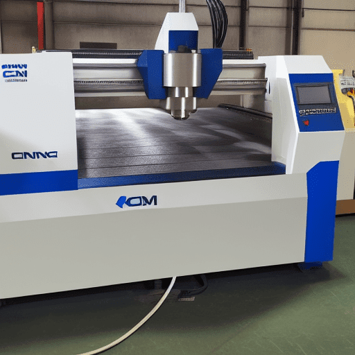
Milling and turning represent two foundational subtractive manufacturing processes, each employing distinct kinematic principles to remove material from a workpiece. These methods are critical for shaping raw stock into precision components across various industries.
Fundamental Kinematics: Cutter vs Workpiece Rotation
The primary distinction between milling and turning lies in the rotational element. Milling operations involve a rotating cutting tool that engages a stationary or slowly moving workpiece. The tool’s rotation provides the necessary cutting action, while the workpiece’s movement dictates the geometry being formed.
Conversely, turning operations feature a rotating workpiece, typically held in a chuck or collet, while a stationary or linearly moving cutting tool removes material. The workpiece’s rotation generates the primary cutting speed, and the tool’s feed motion defines the part’s profile. This fundamental difference dictates machine design and part capabilities.
Consider a typical end mill in a milling machine; its flutes spin at high RPMs, advancing into the material. In a lathe, a cylindrical bar stock spins rapidly, and a single-point tool shaves material from its circumference or face. This core kinematic variance underpins all subsequent operational differences.
Part Geometry and Profile Generation
| Feature | Milling | Turning |
|---|---|---|
| Primary Motion | Rotating Cutter | Rotating Workpiece |
| Tool Type | Multi-point (End Mills, Face Mills) | Single-point (Inserts, Brazed Tools) |
| Typical Part Geometry | Flat surfaces, 3D profiles, pockets, slots | Cylindrical, conical, spherical (external/internal) |
| Machine Axes | X, Y, Z (often A, B, C for multi-axis) | X, Z (sometimes Y, live tooling) |
| Workholding | Vises, clamps, custom fixtures on table | Chucks, collets, faceplates |
| Surface Finish (Ra) | 32-125 microinches (general), 8 microinches (precision) | 16-63 microinches (general), 4 microinches (precision) |
| Standard Tolerances | ±0.002 to ±0.005 inches | ±0.001 to ±0.003 inches |
Milling excels at producing flat surfaces, complex three-dimensional contours, slots, pockets, and intricate features on non-cylindrical parts. The ability of the milling cutter to move along multiple axes (X, Y, Z, and often rotational A, B, C) allows for the creation of diverse geometries, including freeform shapes and internal features.
Turning is inherently suited for generating cylindrical or conical geometries, such as shafts, bushings, and threaded components. The workpiece’s rotation ensures concentricity, making it ideal for parts requiring precise rotational symmetry. While some advanced turning centers can perform limited milling operations with live tooling, their primary function remains rotational part creation.
For instance, a turbine blade, with its complex aerodynamic curves, is typically machined through multi-axis milling. A simple bolt, requiring a perfectly round shank and precise threads, is a classic turning application. Each process is optimized for specific geometric outcomes.
Tooling Principles: Multi-Point vs Single-Point Cutting
Milling predominantly employs multi-point cutting tools, such as end mills, face mills, and slab mills. These tools feature multiple cutting edges (flutes) that sequentially engage and disengage with the workpiece material. This intermittent cutting action distributes the cutting forces and heat across several edges, enhancing tool life and material removal rates.
Turning, by contrast, primarily utilizes single-point cutting tools, often in the form of indexable inserts or brazed carbide tools. Only one cutting edge is actively engaged with the workpiece at any given moment. This concentrated cutting action allows for precise control over chip formation and surface finish, particularly on continuous cuts.
The choice between multi-point and single-point tooling significantly impacts chip load, heat generation, and the overall dynamics of the machining process. Multi-point tools are generally more robust for roughing, while single-point tools offer superior control for finishing passes.
Machine Axis Configurations and Workholding
Milling machines typically feature an X-Y-Z Cartesian coordinate system, where the table moves in X and Y, and the spindle (or head) moves in Z. More advanced machines, like 5-axis CNC mills, incorporate additional rotary axes (A, B, C) to orient the cutting tool or workpiece, enabling complex geometries and single-setup machining. Workholding often involves vises, clamps, or custom fixtures mounted on the machine table.
Turning centers, or lathes, are fundamentally two-axis (X-Z) machines. The X-axis controls the tool’s radial movement (diameter), and the Z-axis controls its axial movement (length). Modern CNC turning centers frequently include a turret for rapid tool changes and may feature Y-axis capabilities and live tooling for off-center drilling or milling operations. Workholding is typically achieved with three-jaw or four-jaw chucks, collets, or faceplates.
The distinct axis configurations directly influence the types of parts each machine can efficiently produce. A milling machine’s table provides a broad, flat surface for securing irregular workpieces, while a lathe’s chuck securely grips cylindrical stock for rotation.
Process Characteristics and Material Removal
Milling operations often involve interrupted cuts, where the cutting edges repeatedly enter and exit the material. This can lead to fluctuating cutting forces and requires tools designed for impact resistance. Typical surface finishes for general milling range from 32 to 125 microinches Ra, though precision milling can achieve finer finishes down to 8 microinches Ra. Standard milling tolerances generally fall within ±0.002 to ±0.005 inches (±0.05 to ±0.127 mm), with high-precision applications reaching ±0.0005 inches (±0.0127 mm).
Turning typically involves continuous cutting, resulting in more stable cutting forces and consistent chip formation. This often leads to superior surface finishes, commonly ranging from 16 to 63 microinches Ra, with precision turning achieving 4 microinches Ra or better. Standard turning tolerances are often tighter than milling, typically ±0.001 to ±0.003 inches (±0.025 to ±0.076 mm), with precision turning capable of ±0.0002 inches (±0.005 mm).
Feeds and speeds vary significantly based on material, tool type, and desired finish. For instance, milling aluminum with a carbide end mill might use surface speeds of 800-2000 SFM and feed rates of 0.003-0.010 IPT. Turning 304 stainless steel with a carbide insert could involve surface speeds of 300-600 SFM and feed rates of 0.005-0.015 IPR. These parameters are critical for optimizing material removal and tool life.