
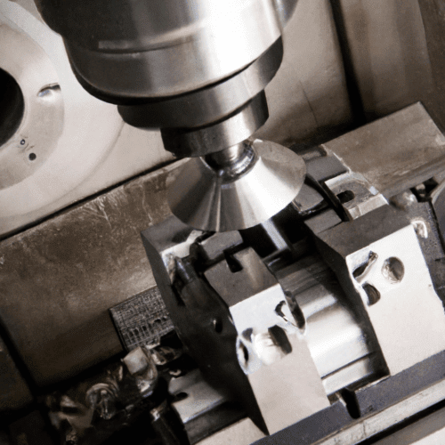
Comparing the inherent difficulties between CNC milling and turning operations reveals distinct challenges across various technical domains. Both subtractive manufacturing processes demand precision, but their fundamental kinematics and part geometries dictate differing levels of complexity for engineers and machinists.
Understanding these operational differences is crucial for optimizing production, selecting appropriate machinery, and developing robust manufacturing strategies. The choice between milling and turning, or a combination thereof, significantly impacts tooling, programming, and overall project feasibility.
Geometry Complexity and Feature Generation
Milling operations excel at producing intricate, multi-faceted geometries, often involving non-rotational features, pockets, slots, and complex contours. Modern 3-axis, 4-axis, and 5-axis milling machines can create highly organic and freeform surfaces, making them indispensable for aerospace components, molds, and medical implants.
Generating these complex shapes requires sophisticated toolpath strategies, often involving simultaneous movement across multiple axes. The ability to machine from various angles without re-fixturing significantly enhances geometric freedom but introduces substantial programming and setup challenges. Parts with internal features, undercuts, or thin walls are routinely produced via milling.
Turning, conversely, is fundamentally designed for parts with rotational symmetry. It efficiently creates external and internal diameters, tapers, threads, and grooves on cylindrical or conical workpieces. While highly effective for these geometries, traditional 2-axis turning is limited to features concentric with the part’s axis of rotation.
The introduction of live tooling in turn-mill machines bridges this gap, allowing for off-center drilling, milling flats, and cross-drilling on a turned part. This hybrid capability significantly expands the geometric possibilities of turning, albeit at the cost of increased machine complexity and programming demands, approaching the intricacy of milling for certain features.
Workholding and Setup Demands
| Operation Type | Tool Material/Coating | Cutting Speed (SFM/m/min) | Feed Rate (IPR/mm/rev or IPT/mm/tooth) |
|---|---|---|---|
| Milling (Roughing) | Carbide (TiAlN) | 400-800 SFM (120-240 m/min) | 0.004-0.008 IPT (0.1-0.2 mm/tooth) |
| Milling (Finishing) | Carbide (AlCrN) | 600-1000 SFM (180-300 m/min) | 0.002-0.004 IPT (0.05-0.1 mm/tooth) |
| Turning (Roughing) | Carbide Insert (PVD TiAlN) | 500-900 SFM (150-275 m/min) | 0.010-0.020 IPR (0.25-0.5 mm/rev) |
| Turning (Finishing) | Carbide Insert (CVD TiCN) | 600-1100 SFM (180-335 m/min) | 0.003-0.008 IPR (0.07-0.2 mm/rev) |
Workholding in milling often presents significant challenges due to the diverse shapes and sizes of parts, coupled with the need to access multiple faces. Vises, clamps, custom jigs, and fixtures are common, frequently requiring multiple setups to machine all necessary features. Precision alignment for each setup is critical to maintain tight tolerances across the entire part.
Securing irregular or thin-walled components without inducing distortion or chatter demands careful fixture design and clamping force distribution. Vacuum chucks, magnetic chucks, and hydraulic clamping systems offer advanced solutions for delicate or complex parts, minimizing manual intervention and improving repeatability.
Turning workholding typically involves chucks, collets, or faceplates, which inherently provide strong, concentric clamping for rotational parts. While generally simpler for basic cylindrical components, challenges arise with long, slender shafts that require steady rests or tailstock support to prevent deflection and chatter.
Maintaining concentricity and minimizing runout are paramount in turning, especially for high-precision components. For parts requiring secondary operations or features not perfectly concentric, specialized fixtures or a transition to a milling operation may be necessary, adding to the overall process complexity.
CAM Programming and Toolpath Generation
CAM programming for milling is generally more complex, particularly for 3D and 5-axis applications. Engineers must define intricate toolpaths for roughing, semi-finishing, and finishing operations, considering tool engagement, step-overs, step-downs, and collision avoidance. Advanced CAM software includes features like high-speed machining (HSM) toolpaths, adaptive clearing, and feature recognition to optimize material removal and surface quality.
Simulating complex milling toolpaths is essential to detect potential collisions between the tool, holder, workpiece, and machine components. This iterative process of programming, simulating, and refining can be time-consuming, especially for novel or highly complex part geometries.
Turning CAM programming, for standard 2-axis operations, is comparatively straightforward. It involves defining turning, facing, grooving, and threading cycles, often utilizing canned cycles within the CNC controller. The linear nature of most turning movements simplifies toolpath generation and collision detection.
However, programming for turn-mill machines, especially those with multiple turrets and spindles, introduces significant complexity. Synchronizing operations between tools, managing live tooling movements, and optimizing cycle times require advanced CAM capabilities and a deep understanding of machine kinematics. This hybrid programming can rival the difficulty of multi-axis milling.
Cutting Tool Selection and Performance
Milling operations demand a vast array of cutting tools, including end mills, face mills, ball nose cutters, and specialized form tools, each with specific geometries, coatings, and flute counts. Tool material selection, such as carbide, HSS, or ceramic, depends on the workpiece material, desired surface finish, and material removal rates.
Optimizing feeds and speeds in milling is critical to manage chip evacuation, heat generation, and tool life, especially in deep pockets or high-speed applications. Modern coatings like TiAlN or AlCrN significantly extend tool life and allow for higher cutting parameters, but their selection requires careful consideration of the specific application.
Turning primarily utilizes indexable inserts, which come in a multitude of shapes (e.g., CNMG, WNMG, CCMT), chip breakers, and coatings tailored for specific operations like roughing, finishing, or parting. The insert’s geometry and grade are chosen based on the workpiece material, desired surface finish, and chip control requirements.
While the variety of turning tools might seem less extensive than milling, the nuances of insert selection for optimal chip formation and surface integrity are highly technical. Achieving precise dimensions and fine finishes often hinges on selecting the correct insert geometry and applying appropriate feeds and speeds. Below is a comparison of typical cutting parameters for machining 1045 steel:
Process Control and Tolerances
Achieving tight tolerances in milling often requires meticulous attention to machine rigidity, tool deflection, thermal expansion, and vibration. For features requiring ±0.0005 inches (±0.0127 mm) or tighter, environmental control, advanced probing, and on-machine measurement systems become essential.
Compensating for tool wear and maintaining consistent surface finishes across complex geometries adds another layer of difficulty. The dynamic nature of milling, with varying tool engagement and chip loads, necessitates robust process monitoring and adaptive control strategies to ensure part quality.
Turning can achieve extremely tight tolerances, particularly on diameters and lengths, often reaching ±0.0002 inches (±0.005 mm) or better with precision machines and optimized processes. The continuous cutting action and simpler kinematics generally lead to more predictable tool wear and surface finishes.
However, maintaining these tight tolerances on long, slender parts or those with interrupted cuts can be challenging due to potential deflection and chatter. Thermal stability of the machine and consistent material properties are critical for high-precision turning applications.