
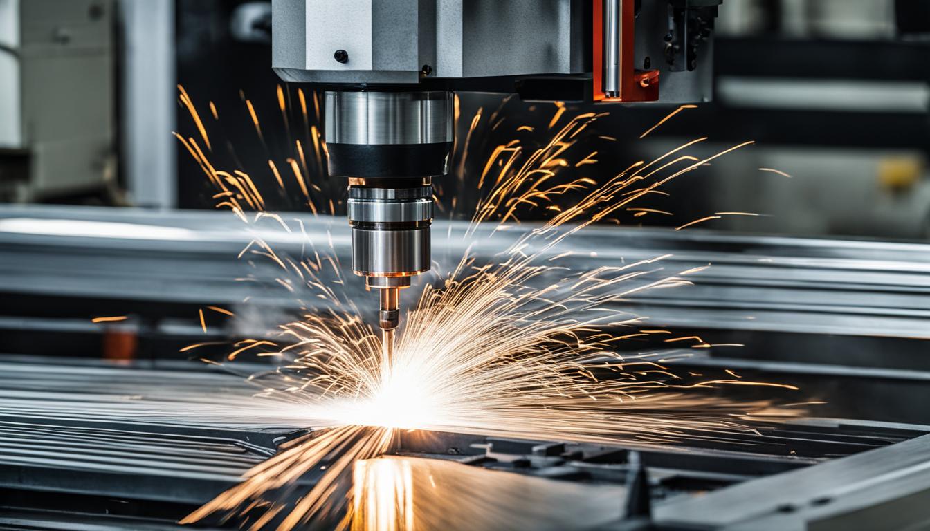
CNC interpolation is the fundamental process by which a machine tool controller generates a continuous, smooth path between discrete programmed points. This critical function translates abstract design data into precise physical motion, enabling the creation of complex geometries on workpieces.
Without interpolation, a CNC machine would only be capable of moving in abrupt, point-to-point steps, severely limiting its ability to produce contoured shapes or intricate features. The controller calculates numerous intermediate points along a defined trajectory, ensuring the cutting tool follows the intended path accurately and efficiently.
The Core Concept of CNC Interpolation
At its heart, interpolation in CNC machining involves the coordinated movement of multiple machine axes to achieve a desired tool position and velocity. The machine’s control system receives G-code commands specifying target coordinates and the type of motion required.
The controller then uses sophisticated algorithms to break down these commands into a series of tiny, incremental movements for each axis. This continuous calculation ensures that all axes arrive at their respective intermediate positions simultaneously, maintaining the programmed feed rate along the interpolated path.
Modern CNC controllers utilize powerful processors to perform these calculations in real-time, often employing look-ahead functions to anticipate upcoming path segments. This predictive capability allows for smoother acceleration and deceleration, minimizing jerk and improving surface finish, especially during high-speed machining operations.
Linear Interpolation (G01) for Straight-Line Cuts
| Feature Type | Standard Tolerance (inches) | Precision Tolerance (inches) |
|---|---|---|
| Linear Dimensions | ±0.005 – ±0.010 | ±0.001 – ±0.003 |
| Hole Diameter | ±0.002 – ±0.005 | ±0.0005 – ±0.001 |
| Flatness/Perpendicularity | 0.005 – 0.010 | 0.001 – 0.003 |
| Circular Features (Radius) | ±0.003 – ±0.007 | ±0.0008 – ±0.002 |
Linear interpolation, commanded by G01, is the most basic form of interpolated motion, used to move the cutting tool in a straight line between two specified points. The G-code command includes the target X, Y, and Z coordinates, along with a feed rate (F).
For example, a command like ‘G01 X100.0 Y50.0 F200’ instructs the machine to move the tool from its current position to X100.0, Y50.0 at a feed rate of 200 units per minute. The controller calculates the necessary velocity for each axis to ensure they reach their endpoints simultaneously, creating a perfectly straight line.
This type of interpolation is essential for milling straight edges, drilling holes, or performing facing operations. Its simplicity makes it highly reliable, forming the backbone of many machining processes where precise linear movements are paramount.
Circular Interpolation (G02/G03) for Arc Generation
Circular interpolation enables the CNC machine to cut arcs and circles, a capability crucial for producing rounded features, fillets, and bores. G02 commands clockwise (CW) motion, while G03 specifies counter-clockwise (CCW) motion.
These commands require not only the endpoint coordinates but also information about the arc’s center. This is typically provided using either the radius (R) parameter or the incremental distances (I, J, K) from the start point to the arc center along the X, Y, and Z axes, respectively.
For instance, ‘G02 X50.0 Y25.0 I25.0 J0.0 F150’ would create a clockwise arc ending at X50.0 Y25.0, with its center 25 units in the positive X direction from the start point. The controller continuously calculates points along the arc’s circumference, maintaining the programmed feed rate and ensuring a smooth curve.
Axis Motion Synchronization and Path Generation
Effective axis motion synchronization is paramount for accurate contouring, especially in multi-axis machining. The CNC controller must precisely coordinate the movement of all active axes to ensure the tool follows the programmed path without deviation.
This synchronization is achieved through sophisticated servo control systems that constantly monitor and adjust each axis’s position and velocity. Any discrepancy between the commanded and actual position is immediately corrected, maintaining the integrity of the interpolated path.
CNC path generation begins in Computer-Aided Manufacturing (CAM) software, where the designer defines the part geometry and tool paths. The CAM system then generates the G-code, which is a series of discrete points and interpolation commands that the CNC controller interprets to create the continuous tool motion.
Smooth Curve Contouring Mathematics
While linear and circular interpolation are foundational, they have limitations for highly complex, free-form curves. For these applications, advanced mathematical models are employed to achieve truly smooth contouring.
Non-Uniform Rational B-Splines (NURBS) are a widely adopted mathematical representation for generating complex curves and surfaces in CAD/CAM systems. NURBS curves offer excellent flexibility and control, allowing for the creation of highly intricate geometries with superior surface quality.
When a CNC controller supports NURBS interpolation, it can directly interpret NURBS data from the CAM system, generating a tool path that precisely follows the mathematical definition of the curve. This eliminates the need to approximate complex curves with numerous short linear or circular segments, resulting in smoother motion and reduced program size.
Precision and Tolerances in Interpolated Paths
The accuracy of interpolated paths is influenced by several factors, including the machine’s mechanical rigidity, the resolution of its encoders, the tuning of its servo drives, and the processing power of the CNC controller. High-precision machining demands tight control over these elements.
Standard tolerances for CNC machining vary significantly based on the material, machine capability, and specific operation. General machining often aims for tolerances within ±0.005 inches (±0.127 mm), while precision applications can achieve much tighter figures.
Achieving and maintaining these tolerances requires regular machine calibration, proper tool selection, and optimized cutting parameters. The interpolation capabilities of the controller play a direct role in how closely the actual tool path adheres to the theoretical path.