
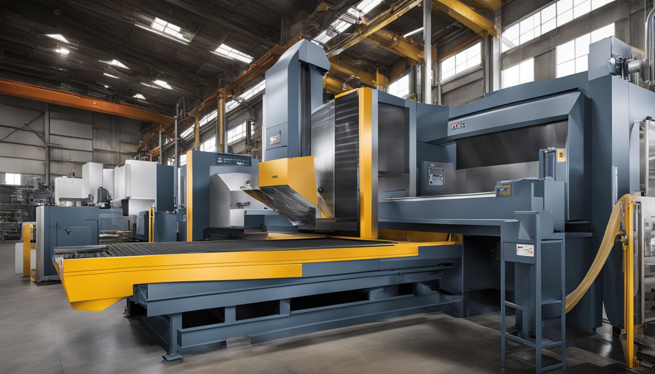
Precision milling operations demand a systematic approach to achieve optimal results in accuracy, surface finish, and efficiency. Each stage, from securing the workpiece to executing the final cuts, requires meticulous attention to detail and adherence to established engineering practices. Understanding these fundamental steps is critical for any tooling engineer or machinist aiming for consistent, high-quality output.
The milling process, a core subtractive manufacturing technique, involves removing material from a workpiece using rotating multi-point cutting tools. Modern CNC machines automate much of this, yet the foundational principles remain constant. Proper execution of these steps directly impacts tool life, part integrity, and overall production costs.
Mount Workpiece Securely
Securing the workpiece is the foundational step in any milling operation, directly influencing machining stability and final part accuracy. Inadequate workholding can lead to chatter, poor surface finish, dimensional inaccuracies, and even catastrophic part ejection. The chosen method must counteract all anticipated cutting forces, including lateral and lifting forces.
Common workholding solutions include vises, clamps, custom fixtures, and vacuum tables. Vises are a primary choice for block-shaped materials, offering robust clamping force. For optimal grip, ensure the workpiece surfaces are parallel; otherwise, clamping force can be significantly reduced, leading to instability.
Clamps, such as top or edge clamps, provide versatility for irregularly shaped parts or when full top-surface access is required. Direct fastening, using bolts to secure the workpiece to a fixture plate or machine bed, offers extreme rigidity. Vacuum clamping is ideal for flat, thin materials, providing uniform holding force across a large surface area without obstructing the tool path.
When using vises, proper torque application is essential; for instance, larger, rigid vises often require torquing to 60 ft-lbs for secure clamping. Always verify that clamps and fixtures are positioned outside the toolpath to prevent collisions and are within the machine’s Z-height limits.
Install Selected Cutting Tool
| Material | Tool Type | Typical SFM (ft/min) | Typical Chip Load (IPT) |
|---|---|---|---|
| Aluminum Alloys | Carbide End Mill | 600-1200 | 0.003 – 0.006 (1/4″ dia) |
| Mild Steel | Carbide End Mill | 100-500 | 0.0005 – 0.002 |
| Stainless Steel | Carbide End Mill | 40-150 | 0.0005 – 0.002 |
| Brass | Carbide End Mill | 250-500 | 0.001 – 0.003 |
Selecting and installing the correct cutting tool is paramount for successful milling. The tool’s material, geometry, and coating must align with the workpiece material, desired surface finish, and specific machining operation. Carbide end mills, for example, are frequently chosen for their hardness and heat resistance in various materials.
Tool holders play a critical role in maintaining tool rigidity and minimizing runout. Common types include collet chucks, end mill holders, hydraulic toolholders, and shrink-fit holders. Shrink-fit holders offer superior grip and balance, significantly extending tool life, especially in high-RPM applications.
Minimizing tool runout, the deviation between the tool’s actual rotation axis and its intended center, is crucial for precision. Even slight runout, exceeding 0.001-0.002 inches for standard milling or 0.0005 inches for finishing, can lead to uneven tool wear, poor surface finish, increased vibration, and reduced tool life. Precision applications often target runout below 0.0002-0.0005 inches.
Always ensure the tool shank and holder taper are clean and free of debris before installation. Properly seat the tool and tighten the holder to the manufacturer’s specifications. After installation, measure the tool length offset accurately, often using a tool setter or probe, to inform the CNC control of the tool’s exact position relative to the spindle face.
Set Work Coordinate Zero
Establishing the Work Coordinate System (WCS) zero point is a critical step that links the part’s design geometry to the physical machine space. The CNC machine operates within its own Machine Coordinate System (MCS), which has a fixed home position. Work offsets, typically designated as G54 through G59, bridge the gap by defining the part’s zero point relative to the machine’s zero.
This separation allows a single G-code program to be used for multiple parts or setups by simply changing the work offset values at the machine control, rather than rewriting the entire program. For example, if multiple vises are on the table, each can be assigned a unique work offset (e.g., G54, G55, G56) to machine identical parts sequentially.
Methods for setting the work offset zero include mechanical edge finders, electronic edge finders, and touch-off probes. Probes offer high accuracy and can automate the process, reducing human error. The process involves locating a specific feature on the workpiece (e.g., a corner, an edge, or a centerline) and entering its machine coordinates into the chosen G-code offset register (X, Y, Z separately).
For the Z-axis, the zero point is typically set to the top surface of the workpiece or a known fixture height. Accurate work offset setting is fundamental for achieving correct part dimensions and preventing collisions.
Configure Spindle Speed and Feeds
Optimizing spindle speed (RPM) and feed rate (IPM) is essential for efficient material removal, extended tool life, and desired surface finish. These parameters are interdependent and depend on several factors: workpiece material, cutting tool material and geometry, tool diameter, number of flutes, and machine rigidity.
Spindle speed (RPM) is calculated using the desired surface feet per minute (SFM) and the tool diameter. The formula is RPM = (SFM × 3.82) / Diameter. Feed rate (IPM) is then determined by RPM, the number of flutes, and the chip load (inches per tooth, IPT). The formula is IPM = RPM × IPT × Number of Flutes.
Chip load is the thickness of material removed by each cutting edge per revolution and is a critical factor. Too low a chip load can cause rubbing, generating excessive heat and premature tool wear, while too high can lead to tool breakage. Recommended chip loads vary significantly by material and tool diameter; for instance, carbide end mills in aluminum typically range from 0.003-0.006 IPT for 1/4″ cutters.
Modern CAM software often provides initial feeds and speeds, but fine-tuning based on real-world observations (chip formation, sound, surface finish) is crucial. For aluminum, typical RPMs range from 8,000–12,000 with feeds of 40–80 IPM, while harder materials like steel require lower SFM and adjusted chip loads.
Execute Milling Passes
Executing milling passes involves a strategic approach to material removal, typically divided into roughing and finishing operations. Roughing aims to remove the bulk of material quickly, often with higher depths of cut and feed rates, leaving a small amount for the finishing pass. Finishing operations prioritize surface quality and dimensional accuracy, using lighter cuts and optimized parameters.
The choice between climb milling (down milling) and conventional milling (up milling) significantly impacts the cutting process. Climb milling, where the cutter rotates in the same direction as the workpiece feed, generally offers a better surface finish, longer tool life, and lower cutting forces. This is because the chip thickness starts at its maximum and gradually thins, reducing friction and heat.
Conversely, conventional milling, with the cutter rotating opposite to the feed, starts with a thin chip that thickens, leading to more rubbing, higher heat, and increased tool wear. While climb milling is preferred for finishing and rigid setups, conventional milling can be advantageous for older machines, less rigid setups, or when removing surface scale.
Modern milling strategies include trochoidal milling, a high-efficiency technique characterized by circular tool paths with low radial engagement. This method significantly reduces cutting forces, heat generation, and tool wear, making it ideal for deep slots, hard materials, and increasing material removal rates.
Effective coolant and lubrication strategies are also vital during milling passes. Flood cooling is a common method, but high-pressure through-spindle coolant (TSC) and Minimum Quantity Lubrication (MQL) offer superior chip evacuation, temperature control, and extended tool life, especially in high-speed applications. Water-soluble coolants are often preferred for aluminum, while oil-based coolants provide better lubrication for difficult alloys.