
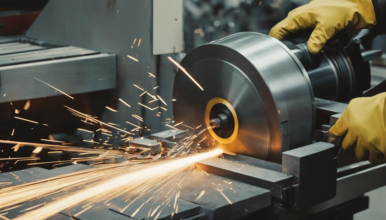
Machining metal is a fundamental subtractive manufacturing process that precisely shapes raw material into a desired form by removing excess material. This method is crucial across industries like aerospace, automotive, and medical device manufacturing, where high precision and durability are paramount. Unlike additive manufacturing, which builds parts layer by layer, subtractive manufacturing starts with a solid block, sheet, or rod and carves away material using various tools.
Modern CNC machining, driven by computer-controlled tools, offers exceptional accuracy and repeatability. It leverages sophisticated software to translate CAD models into precise toolpaths, guiding cutting tools through complex geometries.
Subtractive Material Removal Fundamentals
Subtractive manufacturing encompasses a range of techniques, each designed to remove material efficiently and accurately. Common methods include milling, turning, drilling, grinding, laser cutting, and electrical discharge machining (EDM).
Milling operations utilize rotating cutting tools to remove material from a stationary workpiece, ideal for complex shapes, slots, and holes. Turning involves rotating the workpiece while stationary tools remove material, primarily for creating cylindrical forms like shafts and pulleys. Drilling creates cylindrical holes using rotating drill bits.
These processes rely on the controlled removal of material to achieve the final part geometry. The choice of method depends on the material, desired geometry, and required precision. Modern advancements in CNC technology, including multi-axis and hybrid machining, continue to expand the capabilities of subtractive processes.
Cutting Tool Shear Mechanics and Chip Formation
| Parameter | Standard CNC Machining | Precision CNC Machining |
|---|---|---|
| Linear Tolerance (Metals) | ±0.005 in (±0.127 mm) | ±0.001 in (±0.025 mm) to ±0.002 in (±0.051 mm) |
| Surface Roughness (Ra) | 3.2 µm (125 µin) | 0.2 µm (8 µin) to 0.8 µm (32 µin) |
| Aluminum Cutting Speed | 200-400 m/min | Optimized for specific tool/material combinations |
| Mild Steel Cutting Speed | 80-150 m/min | Optimized for specific tool/material combinations |
Metal is not merely ‘cut’ but rather undergoes a forced separation from itself through plastic deformation, visualized as shearing. As a cutting tool engages the workpiece, material directly ahead of the tool is compressed and sheared under immense pressure. This deformed material then fractures and flows into the space above the tool, forming a chip.
The shear plane is a narrow zone extending from the cutting edge to the workpiece surface where this primary shearing occurs. The shear angle, defined as the angle between the shear plane and the cutting direction, significantly influences cutting forces, tool wear, and surface finish. A smaller shear angle results in a larger shear plane, requiring higher force to remove the chip.
Chip formation physics categorizes chips into three main types: continuous, discontinuous, and continuous with a built-up edge (BUE). Continuous chips, often ribbon-like, form when machining ductile materials at high speeds with sharp tools and minimal friction. These typically yield good surface finishes but can be challenging to dispose of.
Discontinuous or segmental chips are produced when cutting brittle materials like cast iron or hard bronze, or when ductile materials are machined under poor conditions such as low speeds and high friction. A built-up edge forms from tool-chip friction, where chip material adheres to the tool face, eventually breaking off. Lubricants can help prevent BUE formation.
Modern cutting tools feature advanced materials and coatings to optimize chip formation and tool life. Carbide tools are common, with coatings like Titanium Nitride (TiN) for general-purpose work, Titanium Aluminum Nitride (TiAlN) or Aluminum Titanium Nitride (AlTiN) for high-heat applications like stainless steel and titanium, and Diamond-Like Carbon (DLC) for non-ferrous metals and composites.
Coolant Temperature Control
Coolant plays a critical dual role in machining: dissipating heat and providing lubrication. Significant heat is generated by friction between the cutting tool and the workpiece, which can damage both the tool and material, leading to poor finishes and reduced tool life. Coolants absorb and carry this heat away from the cutting zone, maintaining stable temperatures.
Consistent coolant temperature and flow rate are essential for stabilizing thermal conditions during cutting. Temperature-controlled coolant systems prevent thermal cycles that can cause dimensional inaccuracies in the workpiece due to thermal expansion. Through-spindle coolant delivery is particularly effective, removing heat directly at the cutting zone.
Beyond cooling, coolants lubricate the cutting interface, reducing friction and wear on the tool, which enables smoother cutting operations and improves overall cut quality. They also flush away chips and debris from the work area, preventing re-cutting and further heat generation.
Various types of coolants exist, including water-based (soluble, synthetic, semi-synthetic) and non-water-based (straight oils). Water-based coolants offer good cooling but require careful maintenance to prevent microbiological growth. Straight oils provide superior lubrication but have poorer cooling characteristics. Semi-synthetics often offer a balanced solution.
Precision Surface Finishing
Achieving a precision surface finish is paramount in many machined components, directly impacting friction, wear, sealing, lubrication, and overall part performance. Surface roughness describes the microscopic irregularities left on a surface by the cutting process, characterized by peaks and valleys.
Engineers quantify surface roughness using parameters like Ra (Roughness Average) and Rz (Mean Roughness Depth). Ra is the arithmetic mean of all deviations from the mean line, providing an average roughness value. Rz measures the average height difference between the highest peaks and lowest valleys, highlighting surface extremes that Ra might miss.
Standard as-machined surface roughness for CNC parts is typically 3.2 µm Ra (125 µin Ra), which is cost-effective for general applications. Finer finishes, down to 0.2 µm Ra, can be specified for critical functional surfaces, though these require additional machining passes and increased cost.
Achieving specific surface finishes involves careful selection of toolpath strategies, cutting parameters, and tool geometry. Fine machining with sharp tools can achieve Ra 0.8 µm (32 µin). Post-machining processes like bead blasting can further refine the surface, producing a uniform matte or satin finish and reducing visible tool marks.
Modern Machining Practices and Tolerances
Modern CNC machining capabilities continue to advance, driven by digitalization, automation, and smarter factory systems. Multi-axis machines, including 5-axis systems, reduce setup times and errors by machining complex parts in a single setup. Hybrid manufacturing, blending additive and subtractive processes, creates near-net-shape parts finished to tight tolerances.
Standard CNC machining tolerances for most metals typically fall within ±0.005 inches (±0.127 mm). For applications requiring greater accuracy, tight tolerances can reach ±0.002 inches (±0.051 mm), while precision tolerances can be as low as ±0.001 inches (±0.025 mm) in standard milling.
Achieving tighter tolerances demands slower feed rates, well-maintained cutting tools, and meticulous setup. Advanced tooling, including high-performance carbide with specialized coatings, and intelligent tooling systems with embedded sensors for real-time data feedback, are crucial for maintaining precision and predicting tool wear.
Feeds and speeds are critical parameters that must be carefully matched to the material, tool geometry, and machine rigidity. For instance, aluminum typically uses higher cutting speeds (200-400 m/min) and feed rates (300-500 mm/min) compared to mild steel (80-150 m/min cutting speed, 200-400 mm/min feed rate).