
Precision manufacturing relies heavily on subtractive processes, where material is systematically removed from a workpiece to achieve a desired geometry. Among these, turning and milling stand as foundational methods, each offering distinct capabilities and applications. Understanding their core differences is essential for engineers and machinists to select the optimal process for specific part requirements, influencing efficiency, cost, and final product quality.
While both turning and milling utilize computer numerical control (CNC) for automated, highly accurate material removal, their fundamental kinematic principles diverge significantly. This distinction dictates the types of geometries they can efficiently produce and the machine tools employed.
Core Kinematic Distinctions: Workpiece vs. Cutter Motion
Turning operations are characterized by a rotating workpiece, against which a stationary, single-point cutting tool engages to remove material. The workpiece, typically cylindrical, spins rapidly on its axis, while the tool traverses along its surface. This method is inherently suited for creating parts with rotational symmetry.
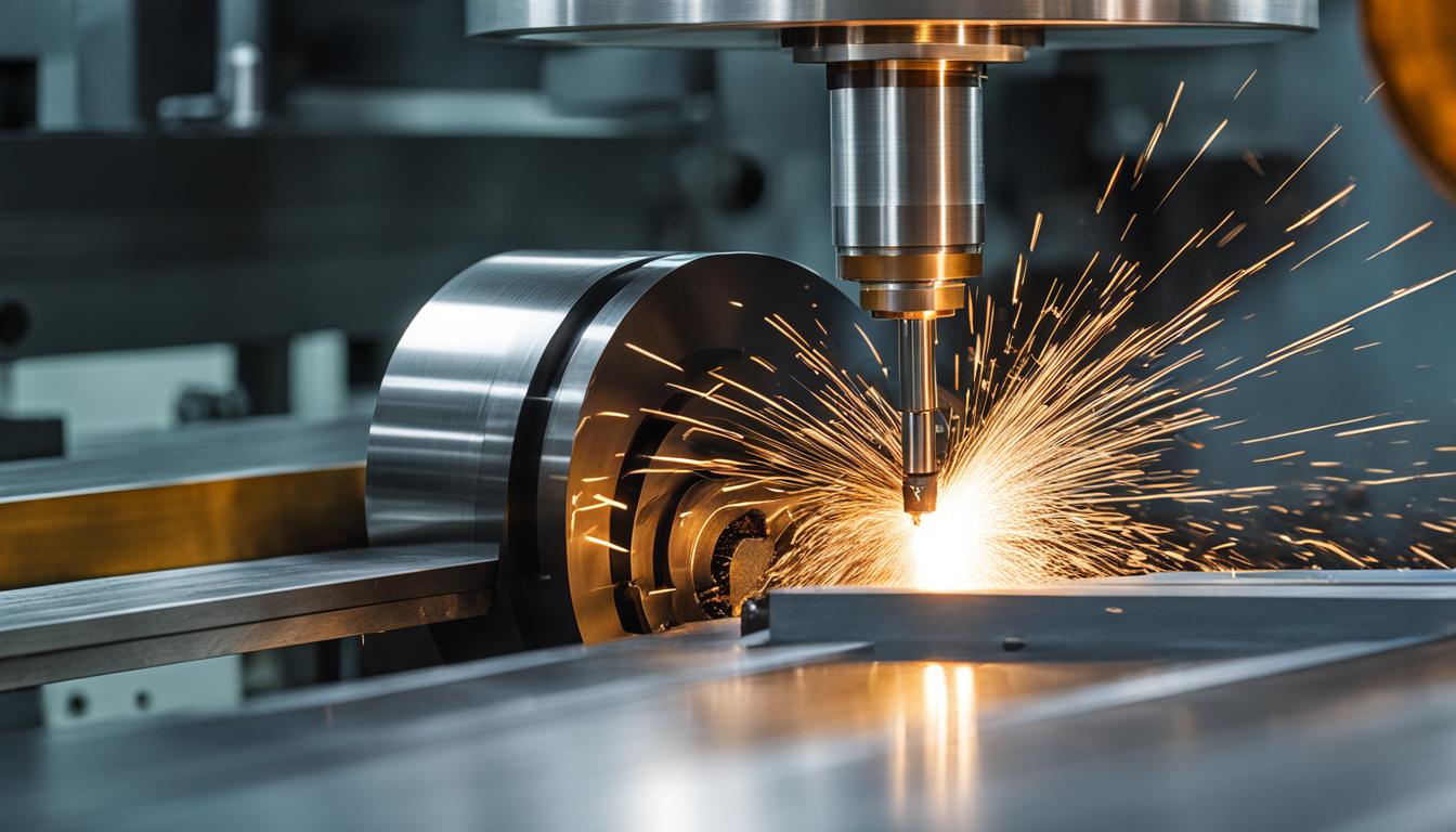
Conversely, milling involves a rotating multi-point cutting tool that removes material from a workpiece, which is generally held stationary or moves along various linear axes. The cutter’s rotation provides the primary cutting action, while its movement relative to the workpiece defines the part’s features. This allows for the creation of complex, non-cylindrical geometries.
This fundamental difference in motion, workpiece rotation in turning versus tool rotation in milling, is the primary differentiator between the two processes. It dictates everything from machine design to the types of parts each process excels at producing.
Machine Architecture: Lathes versus Mills
| Feature | CNC Turning | CNC Milling |
|---|---|---|
| Workpiece Motion | Rotates | Stationary or moves linearly |
| Cutter Motion | Stationary (single-point) | Rotates (multi-flute) |
| Typical Machine | Lathe, Turning Center | Vertical/Horizontal Machining Center |
| Primary Geometry | Cylindrical, conical, spherical | Flat surfaces, slots, pockets, complex 3D contours |
| Tool Type | Single-point inserts | Multi-flute end mills, face mills |
| Standard Tolerance | ±0.005″ (±0.13 mm) | ±0.005″ (±0.13 mm) |
| Precision Tolerance | ±0.001″ (±0.025 mm) or better | ±0.001″ (±0.025 mm) or better |
| Typical Surface Finish (Ra) | 0.8 – 1.6 µm | 1.6 – 3.2 µm |
CNC lathes, also known as turning centers, are the primary machines for turning operations. They typically feature a headstock that holds and rotates the workpiece via a chuck or collet, a tailstock for supporting longer workpieces, and a tool turret that indexes various single-point cutting tools into position. Modern CNC lathes often include live tooling, allowing for secondary milling or drilling operations on the rotating workpiece.
CNC milling machines, or machining centers, come in various configurations, including vertical machining centers (VMCs) and horizontal machining centers (HMCs). These machines feature a spindle that holds and rotates the multi-flute cutting tool, and a worktable that secures the workpiece. The worktable or spindle head moves along multiple linear axes (X, Y, Z) to guide the cutter across the workpiece.
Advanced machining centers can integrate additional rotary axes, transforming a standard 3-axis mill into a 4-axis or 5-axis machine. This expanded kinematic capability allows for machining complex geometries from multiple angles in a single setup, significantly reducing setup times and potential for error.
Geometric Outcomes: Cylindrical Forms and Planar Features
Turning is ideally suited for producing parts with cylindrical, conical, or spherical geometries. Common components manufactured through turning include shafts, pins, bushings, and threaded parts. The continuous cutting action of a single-point tool on a rotating workpiece often results in excellent surface finishes and tight dimensional control on diameters.
Milling excels at creating prismatic parts with flat surfaces, slots, pockets, holes, and intricate three-dimensional contours. Industries from aerospace to medical devices rely on milling for complex components with detailed features.
While turning can achieve very smooth finishes, typically Ra 0.8–1.6 µm, milling generally produces finishes in the range of Ra 1.6–3.2 µm for standard operations. Precision milling can achieve finer finishes, but turning often has an advantage for rotational surfaces.
Tooling Philosophies: Single-Point and Multi-Flute Approaches
Turning predominantly employs single-point cutting tools, which engage the workpiece with one primary cutting edge at a time. These tools are often indexable inserts made from advanced materials like coated carbide, ceramic, cubic boron nitride (CBN), or polycrystalline diamond (PCD). The geometry of the insert and tool holder is crucial for chip control and surface finish.
Milling operations utilize multi-flute cutting tools, such as end mills, face mills, and ball nose cutters, which feature multiple cutting edges. These tools are commonly made from solid carbide, high-speed steel (HSS), or cobalt, often with specialized coatings like TiAlN or AlCrN to enhance tool life and performance. The number of flutes, helix angle, and coating are critical considerations for effective milling.
Selecting appropriate feeds and speeds is paramount for both processes to optimize material removal, tool life, and surface finish. For instance, common cutting speeds for mild steel with carbide tools in turning can range from 150-400 SFM (45-120 m/min) with feed rates of 0.004-0.020 IPR (0.1-0.5 mm/rev).
In milling, carbide end mills in mild steel might operate at 300-800 SFM (90-240 m/min) with feed rates of 0.001-0.005 IPT (0.025-0.125 mm/tooth), depending on the specific operation (slotting, profiling, finishing) and tool diameter.
Advanced Axis Control: Shaping Complex Geometries
Standard CNC lathes typically operate with two axes: X (radial movement for diameter) and Z (axial movement for length). More advanced turning centers incorporate a C-axis, which allows for precise rotational positioning of the main spindle, enabling features like cross-drilling or milling flats on the workpiece.
Further enhancing turning capabilities, the Y-axis provides off-center linear movement perpendicular to the X and Z axes. This enables true milling and drilling operations on the face or diameter of a turned part, often eliminating the need for a secondary milling setup.
Milling machines commonly start with three axes (X, Y, Z) for linear movement. Four-axis milling adds a rotary axis (often designated A or B) that allows the workpiece to be rotated or indexed, facilitating machining on multiple sides or creating helical features.
Five-axis milling introduces two rotary axes, enabling simultaneous movement in all five axes. This capability allows the cutting tool to approach the workpiece from virtually any angle, facilitating the creation of highly complex, organic shapes, deep undercuts, and intricate impellers in a single setup. This significantly reduces cumulative errors and setup times.
Modern engineering practices in both turning and milling leverage advanced CAM software for complex toolpath generation, high-pressure coolant systems for improved chip evacuation and tool life, and integrated automation solutions like robotics for part loading and unloading. These advancements contribute to higher precision, efficiency, and repeatability across diverse manufacturing applications.
Standard machining tolerances for both CNC milling and turning typically range from ±0.005 inches (±0.13 mm) for most general applications. However, with precision machining, tighter tolerances of ±0.001 to ±0.002 inches (±0.025 to ±0.051 mm) are achievable, especially for critical features or specific materials like aluminum and brass. Achieving these tighter tolerances often requires controlled environments, stable fixturing, and specialized inspection methods.