
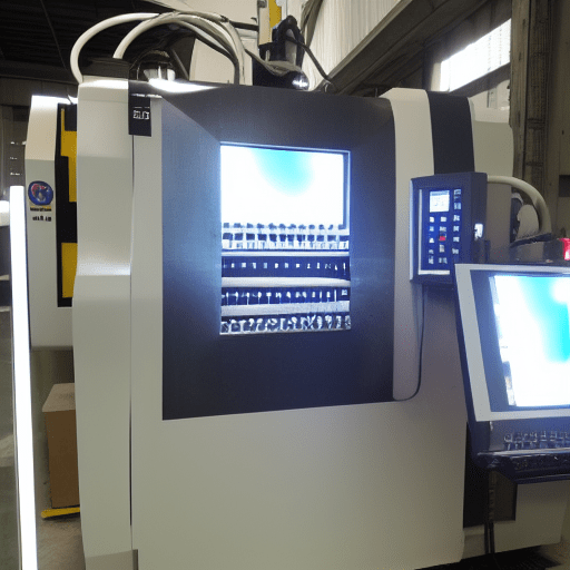
Turning is a fundamental subtractive manufacturing process that precisely shapes cylindrical workpieces. This machining method involves rotating the workpiece at high speed against a stationary, single-point cutting tool. The controlled interaction between the rotating material and the tool progressively removes material, creating the desired external or internal features.
This process is widely utilized across industries for producing components such as shafts, pins, bushings, and threaded bodies. Both manual lathes and advanced Computer Numerical Control (CNC) turning machines execute these operations, with CNC systems offering superior precision for exact part measurements.
The Core Principle of Turning
The operational foundation of turning centers on the rotational motion of the workpiece, which is securely held in a chuck or collet within the lathe’s headstock. This workpiece rotation constitutes the primary cutting motion. Simultaneously, a single-point cutting tool advances linearly along one or more axes, providing the secondary feed motion.
As the cutting tool engages the rotating material, it shears away excess stock, gradually forming the intended cylindrical geometry. The tool’s movement can be longitudinal, parallel to the workpiece’s rotational axis (Z-axis), or transverse, perpendicular to it (X-axis), or a combination of both, enabling diverse shapes and features.
This controlled material removal allows for various operations, including straight turning to reduce diameter, facing to create flat end surfaces, and boring to enlarge internal holes. The precision of the final part depends critically on the synchronized relationship between the rotating workpiece and the tool’s controlled path.
Mechanics of Single-Point Cutting
| Parameter | Typical Value / Range | Notes |
|---|---|---|
| Standard Machining Tolerance | ±0.005 in (±0.13 mm) | For general-purpose parts |
| Precision Machining Tolerance | ±0.002 in (±0.051 mm) | For tight fits and critical features |
| Aluminum Cutting Speed (Carbide) | 600-1200 SFM (200-400 m/min) | Higher speeds for softer materials |
| Mild Steel Cutting Speed (Carbide) | 350-600 SFM (80-150 m/min) | Balanced for strength and machinability |
| Stainless Steel Cutting Speed (Carbide) | 150-350 SFM (60-180 m/min) | Lower speeds to prevent tool wear |
| Roughing Feed Rate (Turning) | 0.25–0.5 mm/rev | For rapid material removal |
| Finishing Feed Rate (Turning) | 0.05–0.15 mm/rev | For surface finish and tolerance |
Single-point cutting tools are characterized by a single, sharp cutting edge that engages the workpiece. This edge applies concentrated shear force, causing the material to deform plastically and separate from the parent body in the form of chips or ‘swarf’. The geometry of the tool, including its rake and clearance angles, significantly influences the cutting efficiency and chip formation.
The cutting action initiates a complex deformation process within the material. As the tool penetrates, a shear plane forms ahead of the cutting edge, where the material undergoes intense plastic deformation. This leads to the formation of a chip that slides along the tool’s rake face.
Forces acting on the cutting tool during turning include tangential, radial, and axial components. The tangential force, often the largest, is responsible for the primary cutting action and power consumption. Radial forces push the tool away from the workpiece, while axial forces act along the workpiece’s centerline. Proper tool rigidity and setup are crucial to manage these forces and maintain dimensional accuracy.
Material Removal Rate Mechanics
Material Removal Rate (MRR) quantifies the volume of material removed from a workpiece per unit of time, typically expressed in cubic millimeters per minute (mm³/min) or cubic inches per minute (in³/min). Optimizing MRR is essential for balancing productivity with tool life and surface finish.
For turning operations, the MRR calculation involves the cutting speed (Vc), feed rate (f), and depth of cut (d). A common formula for turning is MRR = Vc × f × d. This formula highlights how increasing any of these parameters directly increases the rate of material removal.
Engineers must carefully select these parameters based on the workpiece material, tool material, and desired surface finish. Higher MRR is often sought during roughing operations to quickly reduce stock, while finishing passes prioritize lower MRR for superior surface quality and tighter tolerances.
Achieving Precision: Tolerances, Feeds, and Speeds
Precision in turning is governed by strict adherence to engineering tolerances, which define the permissible variation from a nominal dimension. Standard machining tolerances for general-purpose parts often fall around ±0.005 inches (±0.13 mm), while high-precision applications may demand tolerances as tight as ±0.002 inches (±0.051 mm) or even ±0.0005 inches (±0.0127 mm) for reamed holes.
International standards like ISO 2768-1 and ASME Y14.5 provide comprehensive guidelines for general and geometric dimensioning and tolerancing. These standards ensure interchangeability and functionality of machined components by establishing acceptable deviations for linear, angular, and geometric features.
Feeds and speeds are critical parameters that directly influence MRR, tool wear, and surface finish. Cutting speed (Vc), measured in surface feet per minute (SFM) or meters per minute (m/min), is the relative speed between the cutting edge and the workpiece. Feed rate (f), typically expressed in millimeters per revolution (mm/rev) for turning, dictates the tool’s advancement per rotation.
Optimal feeds and speeds vary significantly with material. For instance, aluminum typically allows for higher cutting speeds (200-400 m/min) and feed rates (300-500 mm/min) compared to mild steel (80-150 m/min cutting speed, 200-400 mm/min feed rate) or stainless steel (60-180 m/min cutting speed, 0.05-0.15 mm/rev feed for finishing). Modern CNC machines often utilize constant surface speed (G96) to maintain consistent cutting conditions as the diameter changes.
Here is a general guide for typical turning tolerances and feeds/speeds:
Lathe Spindle Drive Systems
The lathe spindle, located in the headstock, is the critical component responsible for holding and rotating the workpiece at controlled speeds. Its performance directly impacts machining precision, surface finish, and overall productivity. Spindles must maintain high rotational accuracy and provide adequate torque across various speed ranges.
Modern lathe spindles employ several drive mechanisms. Belt-driven spindles transmit power from the motor via belts and pulleys, offering simplicity and high torque at lower speeds. Gear-driven spindles use internal gearboxes for power transmission, providing robust torque for heavy cuts.
Direct-drive spindles connect the motor directly to the spindle shaft, eliminating belts and gears. This design minimizes vibration and improves efficiency, making them suitable for high-speed applications. Built-in motorized spindles integrate the motor within the spindle housing, further enhancing rigidity and thermal stability.
Precision spindles feature advanced bearing systems, often using high-quality angular contact ball bearings or ceramic bearings for ultra-high-speed applications. These bearings support the spindle shaft, ensuring smooth, precise rotation with minimal friction and maximum accuracy, even under significant cutting loads. Modern CNC lathes can achieve spindle speeds ranging from 25 RPM up to 10,000 RPM for ultra-precision work.