
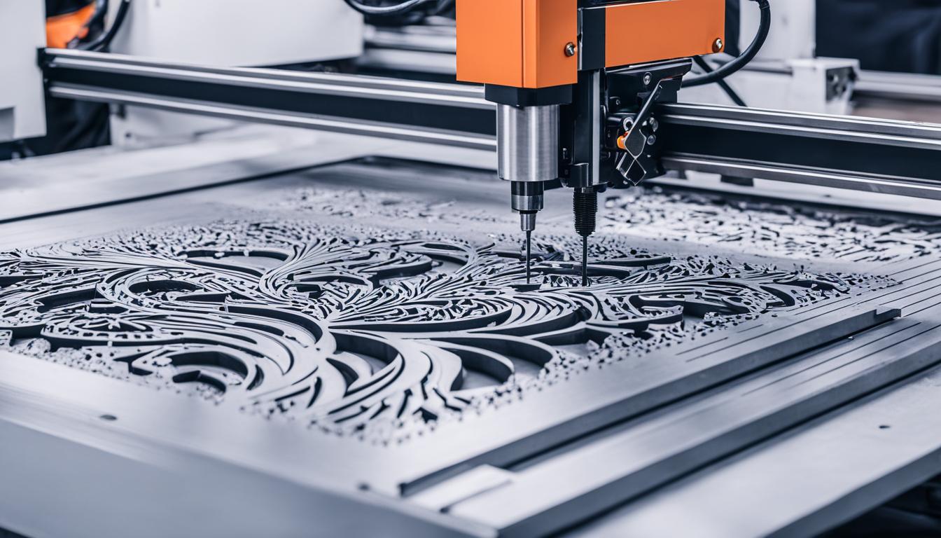
Material cutting, a fundamental process in subtractive manufacturing, involves the controlled removal of material from a workpiece to achieve a desired shape or design. This essential technique underpins countless industrial applications, from aerospace components to medical devices. Achieving precision and efficiency in cutting operations relies on a deep understanding of the underlying physics and engineering principles.
Unlike additive manufacturing, which builds parts layer by layer, subtractive methods begin with a solid block, sheet, or rod and meticulously remove excess material. This approach is highly valued for its ability to produce parts with exceptional accuracy, smooth surface finishes, and compatibility with a broad spectrum of materials, including various metals and engineering plastics.
Shear Deformation Mechanics
The core of material cutting lies in shear deformation mechanics, where the cutting tool exerts mechanical forces that cause the workpiece material to deform and eventually separate. This process primarily involves the material undergoing plastic deformation within a localized region known as the primary shear zone.
As the tool’s rake face pushes against the material, a stress field develops, intensifying closer to the cutting edge. When the shear stress within this field surpasses the material’s yield strength, the workpiece begins to slip along a defined shear plane. This continuous slip, driven by increasing shear stress, leads to the formation of a chip.
The shear angle, defined as the angle between the shear plane and the cutting direction, significantly influences the efficiency of material deformation and detachment. Optimizing this angle minimizes cutting forces, reduces tool wear, and contributes to a smoother surface finish.
Tool Edge Shear Stress and Chip Generation Physics
| Fluid Type | Key Characteristics | Typical Applications |
|---|---|---|
| Straight Oils | Excellent lubrication, poor cooling, undiluted. | Heavy-duty, low-speed operations (broaching, tapping), difficult-to-machine metals. |
| Soluble Oils (Emulsions) | Balanced cooling and lubrication, mixed with water. | General-purpose machining (milling, turning), ferrous and nonferrous metals. |
| Semi-Synthetics | Good balance of cooling and lubrication, less oil than soluble oils. | Moderate to high-speed machining, automotive lines. |
| Synthetics | Superior cooling, excellent for grinding, no mineral oil. | High-speed grinding, applications prioritizing heat removal. |
Concentrated shear stress at the cutting tool’s edge is the direct cause of material failure and subsequent chip formation. The tool’s geometry, particularly its rake angle and edge radius, plays a critical role in how these stresses are distributed and how effectively material is removed.
When the cutting edge engages the workpiece, it forces a thin layer of material to slide up and away from the main body, a phenomenon known as shear failure. This intense localized stress causes the material to exceed its shear strength, breaking away to form a chip.
Chip generation physics categorizes chips into several types, primarily continuous, discontinuous (segmented), and serrated. Continuous chips typically form when machining ductile metals like steel, copper, or aluminum at high cutting speeds. These appear as a continuous ribbon of material flowing up the tool’s rake face.
Conversely, discontinuous or segmented chips are common when machining brittle materials such as brass, bronze, or cast iron. These chips form in small, broken segments due to periodic crack generation within the shear zone. Serrated chips, a hybrid form, often occur in difficult-to-machine materials like titanium alloys, exhibiting localized cracks and a serrated surface.
Subtractive Material Separation Principles
Subtractive material separation encompasses various techniques, each employing distinct mechanisms to remove material from a solid workpiece. CNC machining, a prominent method, utilizes computer-aided design (CAD) models to guide automated cutting tools through processes like milling, turning, drilling, and grinding.
Milling involves rotating cutting tools that remove material from a stationary workpiece, ideal for complex shapes, slots, and holes. Turning, conversely, rotates the workpiece while a stationary cutting tool removes material, primarily for creating cylindrical forms. Drilling creates cylindrical holes using rotating drill bits, a fundamental process for fasteners and fluid passages.
Beyond traditional machining, other subtractive methods include laser cutting, which uses a high-energy laser beam to melt, burn, or vaporize material, and waterjet cutting, which employs a high-pressure stream of water, often mixed with abrasives, to erode material. Each method is selected based on material type, desired precision, and production volume.
Cutting Fluid Heat Reduction
Significant heat generates during machining due to plastic deformation within the primary shear zone and friction at the tool-chip interface. Unmanaged heat accelerates tool wear, increases cutting forces, and degrades surface integrity, making thermal management critical for efficient operations.
Cutting fluids, often called coolants, are essential for mitigating these thermal loads. They reduce heat by absorbing thermal energy from the cutting zone and transporting it away from the tool, workpiece, and chip. Water-based fluids, for instance, possess a higher specific heat capacity, enabling faster heat transfer during high-speed operations.
Beyond cooling, cutting fluids also provide lubrication, reducing friction between the tool and workpiece, which minimizes wear and built-up edge formation. They further aid in chip evacuation, preventing chip recutting that can damage surface finish and cutting inserts. Corrosion inhibitors within fluid formulations protect machine components and finished parts from moisture-induced oxidation.
Modern Engineering Practices and Tolerances
Modern machining practices emphasize precision and efficiency, driven by advancements in tooling materials, coatings, and digital control systems. Carbide tooling, often enhanced with nano-composite coatings like AlTiN, TiAlSiN, and diamond-like carbon, remains crucial for high-performance operations, offering improved wear resistance and surface finish.
Standard CNC machining tolerances typically range from ±0.05 mm to ±0.13 mm, depending on the specific process and material. Achieving tighter tolerances, such as ±0.025 mm or even ±0.01 mm for high-precision milling, significantly increases production costs, often by 15-30% or more.
Material properties profoundly influence achievable tolerances; metals generally allow tighter tolerances than plastics due to their dimensional stability. For instance, aluminum alloys can achieve ±0.05 mm, while engineering plastics typically require wider tolerances of ±0.15 mm to ±0.25 mm. Specifying tolerances only for critical functional features is a key modern practice to optimize manufacturing costs and production time.