
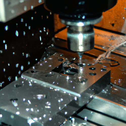
Computer Numerical Control (CNC) milling remains a cornerstone of modern manufacturing, enabling the production of intricate and high-precision components across diverse industries. Achieving optimal results requires a systematic approach, encompassing everything from initial design translation to real-time machining oversight. This guide details the essential technical stages for successful CNC milling operations.
CAD Design Importing for CNC Milling
The journey of a physical part begins with its digital blueprint, typically created in Computer-Aided Design (CAD) software. Importing these designs into a Computer-Aided Manufacturing (CAM) system is the critical first step, demanding careful attention to file format compatibility and data integrity. Neutral file formats are often preferred for seamless data exchange between different software platforms.
Standard for the Exchange of Product Model Data (STEP), identified by ‘.stp’ or ‘.step’ extensions, stands as the most widely accepted 3D file format in CNC machining. This format excels at preserving complex 3D geometry, including assemblies, making it ideal for sharing designs across various CAD and CAM systems.
Initial Graphics Exchange Specification (IGES), with ‘.igs’ or ‘.iges’ extensions, is an older yet still prevalent format, particularly useful for transferring surface and wireframe models. While native CAD files like SolidWorks ‘.sldprt’ or Autodesk Inventor ‘.ipt’ offer rich design data, they often necessitate export to a neutral format for broader CAM software compatibility.
For simpler 2D cutting or engraving tasks, vector formats such as Drawing Exchange Format (DXF) and Drawing (DWG) are commonly employed. Ensuring the chosen file format accurately represents the design’s geometry and maintains precision is paramount to avoid errors in subsequent manufacturing stages.
CAM Toolpath Creation Strategies
| Material | SFM (Surface Feet per Minute) | RPM (Spindle Speed) | Chip Load (per tooth) | IPM (Feed Rate) (3-flute) |
|---|---|---|---|---|
| Aluminum 6061 | 800 – 1200 | 12,200 – 18,300 | 0.002″ – 0.005″ | 73 – 274 |
| Mild Steel 1018 | 200 – 400 | 3,050 – 6,100 | 0.002″ – 0.004″ | 18 – 73 |
Translating a CAD model into machine-executable instructions, known as G-code, is the primary function of CAM software. This stage involves meticulous planning of tool selection, machining strategies, and the calculation of appropriate cutting parameters to ensure efficient material removal and desired surface finish. Modern CAM systems offer advanced algorithms for optimizing toolpaths.
Tool selection is fundamental, considering factors like material, desired finish, and machining operation. Carbide end mills are widely used for their hardness and heat resistance, while High-Speed Steel (HSS) tools are suitable for less demanding applications. The number of flutes on an end mill impacts chip evacuation and rigidity; two or three flutes are common for aluminum, while four or more are often preferred for steels.
Machining strategies vary from roughing, which removes bulk material quickly, to finishing, which focuses on achieving precise dimensions and surface quality. Techniques like adaptive clearing and trochoidal toolpaths are highly effective for maintaining consistent chip load, reducing tool wear, and improving chip evacuation, especially in deep pockets.
Accurate calculation of feeds and speeds is crucial for tool longevity and part quality. Surface Feet per Minute (SFM) or Cutting Speed (Vc) dictates how fast the cutting edge moves across the material, while Feed Rate (IPM) determines the tool’s linear travel. Chip load, the amount of material removed per tooth, is a key parameter to prevent rubbing or overloading the tool.
These values serve as starting points and require fine-tuning based on machine rigidity, tool coating, and coolant application. Simulation within CAM software allows for virtual verification of toolpaths, identifying potential collisions and optimizing cutting sequences before actual machining begins, thereby minimizing costly errors and machine downtime.
Workpiece Clamping and Zeroing
Securely holding the workpiece and accurately establishing its zero point are foundational to achieving dimensional accuracy in CNC milling. Any movement or incorrect datum setting will directly translate into inaccurate parts. The ‘3-2-1 principle’ is a widely adopted method for workpiece location.
This principle involves constraining the workpiece’s six degrees of freedom using a minimum of six points: three points on the primary datum plane, two on the secondary, and one on the tertiary. Common clamping methods include mechanical vises, strap clamps, and toe clamps, which are versatile for general machining. For specific geometries or materials, vacuum clamping for flat, thin materials or magnetic clamping for ferrous metals offer alternative securement.
Establishing the workpiece zero, or ‘work offset,’ defines the origin of the part’s coordinate system relative to the machine’s home position. This is typically achieved using precision tools such as edge finders, dial indicators, or increasingly, automated touch probes. Touch probes offer high accuracy, often within +/- 0.01 mm, and significantly reduce setup time by automatically locating edges and surfaces in X, Y, and Z.
Proper clamping prevents vibration and deflection during cutting, which can lead to poor surface finishes, premature tool wear, and out-of-tolerance parts. The choice of workholding method depends on the workpiece’s size, shape, material, and the forces it will experience during machining.
Tool Offset Measurement and Management
Each cutting tool possesses unique physical dimensions, and the CNC machine must accurately account for these variations to execute programmed toolpaths correctly. Tool offsets are stored correction values within the CNC control that define a tool’s effective length and radius relative to a known reference point.
Tool length offset (H offset) compensates for the distance from the spindle face to the tool’s tip, allowing different length tools to share the same Z-axis program without reprogramming. Tool radius offset (D offset) is crucial for contouring and profiling operations, ensuring the cutter’s edge follows the programmed path accurately.
Measurement of these offsets can be performed manually using height gauges or touch-off blocks, or more efficiently with automated systems. On-machine tool setters, often touch probes or laser systems, automatically measure tool length and diameter directly within the machine’s work envelope. Offline tool presetters measure tools outside the machine, allowing tools to arrive at the CNC with known, pre-calibrated values.
Effective management of tool offset tables is vital, especially in multi-axis machining where tool orientation changes dynamically. Geometry offsets store baseline dimensions, while wear offsets allow for small adjustments during production to compensate for tool wear without altering the main geometry data. Regular verification and organized offset procedures minimize setup errors and maintain dimensional accuracy.
Machining Execution Monitoring
Real-time monitoring during machining execution is essential for ensuring part quality, optimizing tool life, and preventing costly machine failures. This involves observing both the machine’s operational data and the physical cutting process. Effective monitoring strategies combine various data sources for comprehensive insights.
Modern CNC machine monitoring systems integrate controller data, such as spindle load, axis current, and alarm codes, with physical sensor data like vibration and temperature. This combined approach provides a holistic view of machine health and cutting conditions, allowing operators to detect anomalies and make timely adjustments.
Chip evacuation is a critical aspect of monitoring, as inefficient chip removal can lead to tool wear, poor surface finish, and even tool breakage. Strategies to optimize chip evacuation include selecting tools with appropriate flute designs and helix angles, adjusting cutting parameters (higher cutting speeds and feed rates can improve chip flow), and effective coolant application (flood coolant, high-pressure coolant, or air blasts).
Post-machining inspection, often utilizing Coordinate Measuring Machines (CMMs), verifies that parts meet specified tolerances. Standard CNC milling tolerances typically range from ±0.05mm (±0.002″) for general applications to ±0.01mm (±0.0004″) for precision-grade components. Achieving tighter tolerances often requires specialized equipment, careful process control, and a temperature-controlled environment.