
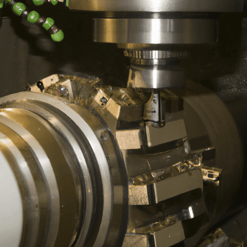
Turning and milling represent fundamental subtractive manufacturing processes, shaping raw material into desired geometries by removing chips. These distinct methods utilize different kinematic principles to achieve precise component features.
Rotational versus Stationary Cutting
The primary distinction between turning and milling lies in the motion of the workpiece and the cutting tool. In turning, the workpiece rotates, while the cutting tool remains largely stationary, engaging the spinning material.
Conversely, milling operations involve a stationary workpiece, securely clamped to a machine table. The cutting action is performed by a rotating multi-point tool, which traverses across the workpiece to remove material.
This fundamental difference dictates the types of geometries each process can efficiently create. Understanding these kinematics is essential for selecting the appropriate machining method for a given part.
Lathe and Mill Processes
| Parameter | CNC Turning (Lathe) | CNC Milling (Mill) |
|---|---|---|
| Workpiece Motion | Rotates | Stationary |
| Tool Motion | Stationary (single-point) | Rotates (multi-point) |
| Primary Geometries | Cylindrical, conical, spherical | Prismatic, flat, complex contours |
| Typical Axes | 2 (X, Z), often 3 (X, Y, Z) | 3 (X, Y, Z), often 4-5+ |
| Common Tolerances (Steel/Aluminum) | ±0.002″ to ±0.005″ (±0.05mm to ±0.127mm) | ±0.002″ to ±0.005″ (±0.05mm to ±0.127mm) |
Lathes are the quintessential machines for turning, designed to produce parts with rotational symmetry. A workpiece is mounted in a chuck or collet and spun at high speeds, while a single-point cutting tool removes material from its outer or inner diameter, or face.
Milling machines, on the other hand, employ rotating multi-flute cutters to remove material from a stationary workpiece. These machines are highly versatile, capable of creating flat surfaces, slots, pockets, holes, and complex three-dimensional contours.
The axes of motion also differ significantly. Lathes typically operate with two primary axes (X and Z) for radial and axial movement, though modern machines often include Y-axis capabilities. Milling machines commonly feature three axes (X, Y, Z) for movement along orthogonal planes, with advanced systems incorporating additional rotational axes.
Cylindrical and Flat Geometries
Turning excels at generating cylindrical, conical, and spherical forms. Components such as shafts, pins, bushings, and threaded parts are ideally suited for lathe operations due to their inherent rotational symmetry.
Milling is the preferred method for producing prismatic parts, which feature flat surfaces, square shoulders, and intricate profiles. Examples include engine blocks, brackets, molds, and complex housings that lack rotational symmetry.
While some overlap exists, the core strength of turning lies in its efficiency for concentric features, whereas milling provides unparalleled flexibility for non-concentric and geometrically complex designs.
Multi-Axis Turn-Mill Centers
Modern manufacturing often leverages multi-axis turn-mill centers, which integrate the capabilities of both lathes and milling machines into a single platform. These advanced machines can perform both turning and milling operations without requiring multiple setups.
These integrated systems typically feature live tooling, allowing rotating tools to be mounted on the turret for milling, drilling, and tapping operations on a rotating or stationary workpiece. Many also incorporate a Y-axis for off-center machining and a B-axis for angular positioning of the milling spindle.
The primary advantage of turn-mill centers is the ability to complete complex parts in a single clamping, significantly reducing cycle times, improving part accuracy by eliminating re-fixturing errors, and minimizing work-in-process inventory.
Programming these sophisticated machines requires advanced CAM software and skilled operators due to the intricate coordination of multiple axes and diverse cutting operations. The investment in such technology is justified by the gains in efficiency and precision for complex components.
Subtractive Manufacturing Techniques
Turning and milling are cornerstones of subtractive manufacturing, a broad category of processes that remove material from a workpiece to achieve a desired shape. This contrasts with additive manufacturing, which builds parts layer by layer.
Effective subtractive machining relies on precise control over material removal rates, surface finish, and dimensional accuracy. Modern engineering practices emphasize optimizing tool paths, selecting appropriate cutting tools, and managing chip evacuation to achieve high-quality results.
Standard tolerances for CNC machining vary based on material, machine capability, and part requirements. For general CNC turning and milling of common materials like aluminum and steel, typical tolerances can range from ±0.002 inches (±0.05 mm) to ±0.005 inches (±0.127 mm), with tighter tolerances achievable on high-precision machines.
Feeds and speeds are critical parameters influencing tool life, surface finish, and material removal rate. These are determined by factors such as workpiece material, tool material, tool geometry, and machine rigidity. Modern CAM software often provides optimized starting parameters, which are then fine-tuned by experienced machinists.