
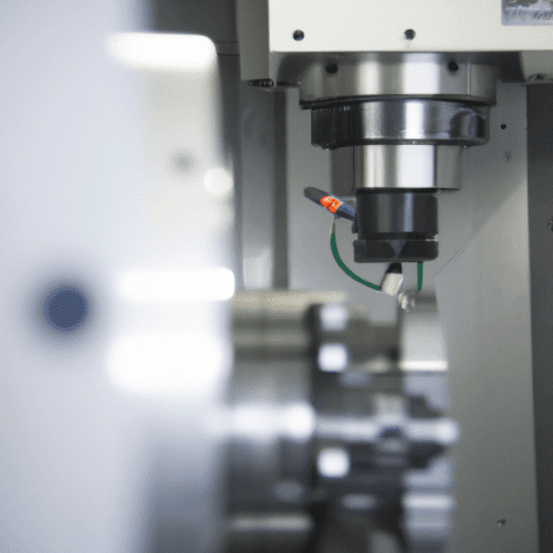
Computer Numerical Control (CNC) represents a fundamental shift in manufacturing, transitioning from manual operation to automated, computer-driven processes. This technology utilizes pre-programmed computer code to dictate the precise movements and functions of machine tools, enabling the production of complex parts with exceptional accuracy and repeatability. Its origins trace back to the 1940s with early numerical control systems, which relied on punched tape for instructions, evolving significantly with the advent of modern computing [4, 9, 11].
CNC machines are essentially motorized tools and platforms controlled by a computer, executing instructions delivered as a sequential program of machine control commands. This automation minimizes human error, boosts efficiency, and facilitates continuous production cycles [8, 35]. The ‘numerical’ aspect refers to the use of numbers for maneuvering tools, encompassing Cartesian coordinates, speeds, and rotational degrees [4].
Computer Numerical Control Fundamentals
At its core, Computer Numerical Control involves a sophisticated interplay between software and hardware to achieve precise material removal or deposition. The process typically begins with a Computer-Aided Design (CAD) model, which is then translated into machine-readable instructions by Computer-Aided Manufacturing (CAM) software [4, 9]. This digital workflow ensures that design intent is accurately communicated to the manufacturing equipment.
A CNC system comprises several key components: a controller, software, and the machine tools themselves. The CNC controller, often referred to as the Machine Control Unit (MCU), acts as the ‘brain,’ interpreting CAD/CAM programs and issuing commands for tool movements and other machine functions [4]. This integrated approach allows for rapid prototyping and efficient mass production, with modifications easily implemented by editing the program rather than retooling physical equipment [4, 13].
Automated Machine Drive Systems
| Nominal Dimension Range (mm) | Linear Tolerance (±mm) | Radius & Chamfer Tolerance (±mm) |
|---|---|---|
| 0.5 up to 3 | 0.10 | 0.20 |
| Over 3 up to 6 | 0.10 | 0.50 |
| Over 6 up to 30 | 0.20 | 1.00 |
| Over 30 up to 120 | 0.30 | – |
| Over 120 up to 400 | 0.50 | – |
| Over 400 up to 1000 | 0.80 | – |
Automated machine drive systems are critical for translating digital commands into precise physical motion within a CNC machine. These systems typically consist of motors, drives, and feedback devices, working in a closed-loop configuration to continuously monitor and adjust position and movement [8, 14]. This constant feedback mechanism is essential for achieving the high accuracy demanded in modern manufacturing.
Servo motors are widely employed in CNC applications due to their high precision, dynamic response, and excellent controllability [18, 27]. They maintain consistent torque across a broad speed range and provide micron-level accuracy through feedback from encoders or resolvers [22]. Direct drive motors, which eliminate mechanical transmission elements like belts or gearboxes, further enhance precision by reducing backlash and friction, making them ideal for high-speed, high-accuracy operations [27].
Stepper motors offer an alternative, operating in an open-loop system where they move without confirming the intended position [41]. While generally less precise than servo systems, they are suitable for applications where cost-effectiveness and simpler control are priorities. The choice between servo and stepper motors depends heavily on the required positional accuracy, speed, and dynamic response of the specific CNC application [41].
G-Code Instructions and Programming
G-code, also known as geometric code or preparatory code, is the primary programming language used to instruct CNC machines [21, 29]. It is a text-based instruction set that dictates how machine tools move, their speed, and other critical machine actions [24]. Each line of G-code, often called a ‘block,’ contains specific commands and parameters that the CNC machine executes sequentially [24, 39].
G-codes primarily control the geometric movements of the machine, such as rapid positioning, linear interpolation, and circular interpolation [21, 29]. M-codes, or ‘miscellaneous codes,’ complement G-codes by controlling non-movement related machine functions, including spindle on/off, tool changes, and coolant activation [21, 26, 37]. Understanding both G-codes and M-codes is fundamental for effective CNC programming.
Common G-code commands include G00 for rapid movement, G01 for linear feed moves, and G02/G03 for clockwise and counter-clockwise circular movements, respectively [21, 29, 30]. Other essential commands manage cutter compensation (G40, G41, G42), tool length compensation (G43), and work offsets (G54) [26]. CAM software typically generates these complex G-code programs automatically from CAD designs, though manual editing and understanding remain valuable skills for machinists [21, 46].
Digital Manufacturing Integration
Digital manufacturing leverages CNC technology as a cornerstone, integrating digital design, simulation, and production into a cohesive workflow. This approach transforms CAD models directly into physical parts with high accuracy and efficiency [9, 32]. The digital thread, a key concept in smart manufacturing, connects data flows across the entire product lifecycle, from design to manufacturing and beyond [1, 6].
The National Institute of Standards and Technology (NIST) defines the digital thread as an extensible, configurable framework for generating actionable information from disparate data sources to inform decision-makers [6]. This framework enables seamless information exchange between systems, ensuring traceability and context throughout the product’s life [6]. It helps manufacturers reduce cycle times and achieve ‘correct parts the first time’ by providing an integrated view of all asset data [1].
Digital manufacturing also incorporates the concept of a ‘Digital Twin,’ a high-fidelity virtual representation of machines, processes, and production environments [42]. This virtual model allows engineers to simulate and validate operations, evaluate toolpaths, and optimize NC programs before any physical machining occurs, significantly reducing the need for prototypes and test runs [42]. This virtualization leads to increased precision and speed in production preparation [42].
Precision Motion Control and Tolerances
Precision motion control is paramount in CNC machining, ensuring that mechanical movements achieve specified positions, velocities, and trajectories with exceptional accuracy and repeatability [14, 25]. This involves orchestrating the electromechanical system to bridge the gap between digital commands and actual physical movement [33]. High-resolution feedback devices, such as encoders, are crucial for this level of control, providing continuous data for real-time adjustments [14, 18].
Achieving tight tolerances is a hallmark of precision CNC machining. Standard CNC machining tolerances typically range from ±0.05 mm to ±0.13 mm for most milling and turning operations [10, 48]. However, precision-grade manufacturing can achieve tolerances as tight as ±0.01 mm, though this requires specialized equipment, careful process control, and often a temperature-controlled environment [20, 48].
The ISO 2768 standard provides general tolerances for linear and angular dimensions that are not explicitly specified on a drawing [2, 5, 7]. This standard categorizes tolerances into four classes: fine (f), medium (m), coarse (c), and very coarse (v) [2, 5]. ISO 2768-m is widely considered the industry standard for most CNC machined parts, balancing precision with manufacturing cost [15]. For critical features requiring precise fit or alignment, custom tolerances or Geometric Dimensioning and Tolerancing (GD&T) are recommended [5, 20].
Feeds and speeds are crucial parameters that directly influence cutting performance, surface finish, tool wear, and machining time [38, 45]. Spindle speed (RPM) dictates how fast the cutting tool rotates, while feed rate refers to how quickly the tool advances through the material [36, 38]. Proper optimization of these parameters is essential to prevent issues like burning, chatter, and premature tool wear, ensuring efficient material removal and high-quality parts [19, 38, 44].
For materials like aluminum, optimal spindle speeds typically range from 8,000 to 12,000 RPM with feed rates of 40 to 80 inches per minute (IPM) [19]. Dense hardwoods, such as walnut, generally perform well with 6,000 to 8,000 RPM and 60 to 100 IPM [19]. These parameters must be carefully matched to the material density, tool geometry, and machine rigidity to achieve the desired results [19, 38].