
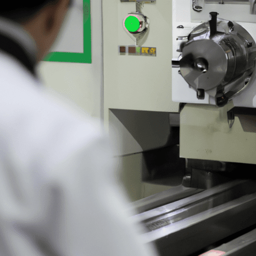
Computer Numerical Control (CNC) machines rely on sophisticated motor systems to achieve the high precision and dynamic performance demanded by modern manufacturing. These motors translate digital commands into precise mechanical movements, directly influencing the accuracy, speed, and surface finish of machined parts. Understanding the distinct characteristics and applications of various motor types is fundamental for optimizing CNC operations.
Stepper Motors versus Servo Motors: the Fundamental Choice
Stepper motors operate by dividing a full rotation into a series of discrete steps, typically 200 steps per revolution for a 1.8° step angle. In an open-loop configuration, the CNC controller sends a sequence of electrical pulses, assuming the motor executes each step without verification. This makes them cost-effective for hobbyist machines and light-duty applications where high precision under varying loads is not paramount.
The primary limitation of open-loop stepper motors is their susceptibility to ‘missing steps’ if the load or cutting force exceeds the motor’s available torque at a given speed. This results in cumulative positioning errors, which can lead to dimensional inaccuracies in the workpiece. Such errors are undetectable by the controller in an open-loop system, potentially scrapping expensive material.
Servo motors, conversely, operate within a closed-loop feedback system, continuously monitoring and correcting their position, speed, and torque in real-time. An integrated feedback device, such as an encoder, provides constant data to a servo drive, which then adjusts the motor’s output to match the commanded position precisely. This architecture ensures high positional accuracy and a fast dynamic response, even under variable load conditions.
A hybrid solution, known as closed-loop stepper motors, incorporates an encoder to provide feedback, mitigating the risk of missed steps inherent in open-loop systems. While offering improved accuracy and repeatability over traditional steppers, they generally do not achieve the same level of dynamic performance or precision as a full servo system with a high-resolution encoder.
Brushless AC Servo Motors: Precision and Power
| Feature | Stepper Motors (Open-Loop) | Servo Motors (Closed-Loop) |
|---|---|---|
| Control System | Open-loop (no feedback) | Closed-loop (with encoder feedback) |
| Precision | Good for light loads, prone to step loss | High positional accuracy, micron-level |
| Torque at Speed | Decreases significantly at higher speeds | Consistent torque across a wide speed range |
| Speed Capability | Moderate to low | High-speed operation without sacrificing accuracy |
| Cost | Lower initial cost | Higher initial cost |
| Maintenance | Low | Very low (brushless types) |
Brushless AC servo motors are the predominant choice for high-performance CNC machines due to their exceptional efficiency, minimal maintenance requirements, and superior power density. Their design eliminates physical brushes and commutators, which are common wear points in older DC servo motors, leading to increased reliability and a longer operational lifespan.
These motors typically feature a permanent magnet rotor spinning within a stator with electromagnetic coils, enabling electrical commutation. This construction allows for very smooth operation with minimal vibration and noise, making them ideal for environments demanding quiet performance and high precision. They can also run at higher voltages and speeds compared to brushed DC servo motors, delivering more power for a given physical size.
In modern CNC systems, brushless AC servo motors are critical for driving the machine axes, facilitating rapid positioning and maintaining accuracy even under varying cutting loads. Their ability to deliver consistent torque across a broad speed range is essential for intricate cuts and complex designs, ensuring steady performance throughout the machining process.
The high ratio of torque to inertia in these servo motors allows for extremely responsive and agile performance, crucial for applications requiring rapid acceleration and deceleration with high precision. This capability ensures that CNC machines can quickly reach desired speeds and precisely control movements, outperforming other motor types in dynamic environments.
Spindle Induction Motors: the Heart of Material Removal
The CNC spindle motor is the core component responsible for driving the cutting tool, converting electrical energy into the mechanical rotation necessary for milling, drilling, routing, grinding, or engraving. These motors are designed to achieve high speeds and torque levels, directly impacting the quality of the surface finish and the efficiency of material removal.
AC induction motors are the most common type used for CNC spindles due to their inherent robustness, reliability, and cost-effectiveness. They operate by generating a magnetic field in the stator windings, which then interacts with the rotor to create torque. Control over their speed and power output is typically managed by a Variable Frequency Drive (VFD).
Spindle motor power ratings vary significantly based on the material being machined. For woodworking and plastics, 0.8 kW to 5 kW motors are generally sufficient, often utilizing air-cooled designs for simplicity. Machining aluminum and light metals typically requires 5 kW to 10 kW, while steel and hard metals often demand 10 kW or more, necessitating water-cooled systems to manage intense heat and maintain performance during prolonged, heavy-duty operations.
Maintaining a consistent RPM under load is critical for achieving smooth finishes and accurate cuts. Spindle motors, especially when paired with VFDs, utilize feedback systems to prevent slowing down during cutting, ensuring stable performance even when encountering tough materials. This precise control over rotational speed is paramount for tool life and workpiece quality.
Closed-Loop Feedback Encoders: Ensuring Accuracy
Encoders are indispensable components in closed-loop CNC systems, providing real-time feedback on the motor’s rotational speed, position, and direction. This continuous stream of data allows the servo drive and CNC controller to make immediate adjustments, ensuring the machine tool follows the programmed path with exceptional precision and repeatability.
Incremental encoders are widely used and typically require a ‘homing’ procedure after power-up to establish a reference point, as they only report position relative to their starting state. These encoders generate a series of pulses as the shaft rotates, with the number of pulses indicating displacement and the frequency indicating speed.
Absolute encoders, conversely, provide a unique digital code for each shaft position, meaning they retain their position data even after power loss. This feature is particularly advantageous for multi-axis machines or vertical axes where maintaining position without recalibration is critical for safety and efficiency. Optical encoders, which use a code disc and light, offer high resolution (17-23 bits) and accuracy, while magnetic encoders are more robust in harsh environments.
Encoder resolution, often expressed in lines per revolution (LPR) or bits, directly impacts the precision of the motion control system. Servo motors commonly utilize encoders with resolutions of 1000-2000 lines per revolution for micron-level accuracy. Higher resolution encoders, such as those offering 12-14 bits (4,096 to 16,384 counts per revolution) for closed-loop steppers or up to 23 bits for high-end servos, enable finer positioning and smoother motion.
Torque Performance Specifications: Driving Machine Dynamics
A motor’s torque-speed curve is a fundamental performance characteristic, graphically illustrating the amount of rotational force (torque) a motor can deliver at any given speed (RPM). This curve is invaluable for engineers to determine if a motor can meet the specific load and speed requirements of a CNC axis, revealing its true performance limits.
Key torque ratings include ‘rated torque,’ which is the continuous torque a motor can produce without overheating, and ‘peak torque,’ representing the short-duration overload capability for acceleration or sudden load changes. ‘Holding torque’ refers to the torque maintained at zero speed, crucial for preventing movement when an axis is stationary.
Inertia matching, the ratio of load inertia to motor inertia, significantly influences the stability and tuning complexity of a servo system. A practical guideline suggests keeping this ratio below 5-10 to simplify control and improve robustness, ensuring the motor can effectively control the attached mechanical load.
Optimal torque performance directly translates to the machine’s dynamic capabilities, including rapid traverse speeds and the ability to handle aggressive cutting forces without compromising accuracy. Modern CNC controllers utilize advanced trajectory planning and jerk-limited acceleration profiles to ensure the motor operates within its torque capabilities, preventing position errors and maintaining high feed rates.