
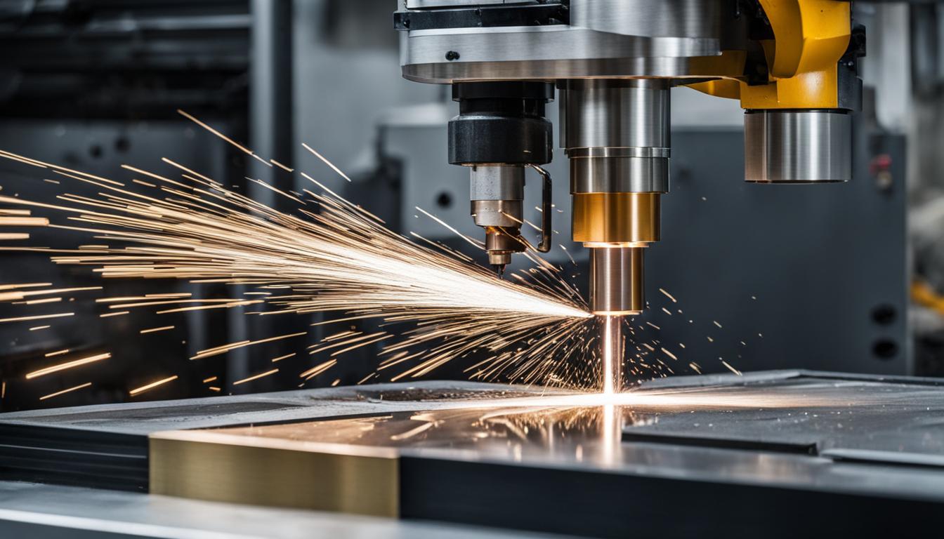
Computer Numerical Control (CNC) machines represent the backbone of modern manufacturing, offering unparalleled precision, repeatability, and automation across diverse industries. These sophisticated systems execute pre-programmed instructions, transforming raw materials into intricate components with minimal human intervention. Understanding the distinct capabilities of various CNC machine types is essential for optimizing production processes and achieving specific engineering outcomes.
Each machine category, from subtractive methods like milling and turning to advanced processes such as electrical discharge machining, possesses unique operational principles and application strengths. Selecting the appropriate CNC technology directly impacts part quality, production efficiency, and overall project cost. This guide explores several prominent CNC machine types, detailing their technical specifications, typical tolerances, and optimal uses.
CNC Vertical Mills
CNC vertical mills are workhorses in subtractive manufacturing, primarily used for shaping solid materials by removing chips with a rotating cutting tool. The spindle, oriented vertically, moves along the Z-axis, while the workpiece typically remains stationary on a table that translates along the X and Y axes. This configuration makes them highly versatile for producing flat surfaces, slots, pockets, and intricate 3D contours.
Modern vertical machining centers (VMCs) often feature 3, 4, or 5 axes of motion, enabling complex geometries and single-setup machining of multi-sided parts. Spindle speeds commonly range from 8,000 to 15,000 RPM, with high-speed variants exceeding 30,000 RPM for fine finishing and small-diameter tooling. Power outputs vary significantly, from 5 HP for smaller machines to 50 HP or more for heavy-duty applications, influencing material removal rates and rigidity.
Standard tolerances for CNC milling typically fall within ±0.05 mm to ±0.13 mm for most operations. Precision-grade milling can achieve ±0.01 mm with careful process control, proper tooling, and experienced operators. For critical features, ultra-high precision can reach ±0.005 mm, often requiring a temperature-controlled environment and advanced inspection methods like Coordinate Measuring Machines (CMMs).
Feeds and speeds are critical parameters, heavily dependent on the material and tooling. For aluminum, carbide end mills might operate with cutting speeds between 250–400 surface feet per minute (SFM). Mild steel typically uses 60–120 SFM, while stainless steel ranges from 40–80 SFM. These parameters are adjusted to maintain an optimal ‘chip load,’ preventing tool wear and ensuring a quality surface finish, which for milling is typically Ra 1.6–3.2 µm.
CNC Turning Lathes
| Machine Type | Primary Function | Typical Tolerances (mm) | Achievable Surface Finish (Ra µm) | Common Materials |
|---|---|---|---|---|
| CNC Vertical Mill | Material removal via rotating tool | ±0.05 to ±0.13 (standard), ±0.01 (precision) | 1.6 – 3.2 | Aluminum, Steel, Stainless Steel, Plastics, Composites |
| CNC Turning Lathe | Cylindrical part creation via rotating workpiece | ±0.13 (standard), ±0.05 (precision) | 0.8 – 1.6 | Aluminum, Steel, Stainless Steel, Brass, Plastics |
| CNC Router Table | Cutting/carving soft materials with rotating tool | ±0.15 to ±0.25 | Visually smooth, less critical Ra | Wood, MDF, Plywood, Plastics, Composites |
| CNC Plasma Cutter | Thermal cutting of conductive metals | ±0.5 to ±1 (standard), ±0.25 (HD plasma) | Rougher, dross-affected edges | Steel, Stainless Steel, Aluminum, Copper |
| Wire EDM Machine | Non-contact erosion of conductive materials | ±0.005 to ±0.01 (multi-pass), ±0.002 (high-precision) | 0.2 – 0.8 | Hardened Tool Steels, Carbide, Titanium, Inconel, Aluminum |
CNC turning lathes are fundamental for creating cylindrical or round features by rotating the workpiece at high speed while a stationary cutting tool removes material. The defining characteristic is that the part spins, and the tool moves, excelling at producing shafts, pins, bushings, and threaded components.
Key specifications include ‘swing over carriage’ (maximum turning diameter), ‘distance between centers’ (maximum workpiece length), and ‘spindle bore’ (maximum bar stock diameter for automated feeding). Spindle speeds can reach up to 6,000 RPM on many machines, with some high-performance models exceeding this for smaller diameters and softer materials. Spindle power, ranging from 5 HP to over 30 HP, is crucial for machining harder materials like stainless steel or titanium.
Standard commercial tolerance for CNC turning is around ±0.13 mm on general diameter features. Precision turning can achieve ±0.05 mm on critical diameters with appropriate tooling and rigid workholding. High-precision applications can reach ±0.025 mm, requiring slower finishing passes and stable conditions. Some advanced systems claim tolerances as tight as ±0.002 mm. Surface finishes typically range from Ra 0.8–1.6 µm.
Feeds and speeds for turning are often expressed in surface meters per minute (m/min) or surface feet per minute (SFM) for cutting speed, and millimeters per revolution (mm/rev) for feed rate. For 304 stainless steel, uncoated carbide tools might use cutting speeds of 100–140 m/min, with roughing feed rates of 0.20–0.40 mm/rev and finishing feed rates of 0.05–0.15 mm/rev. Constant surface speed (G96) programming is common, automatically adjusting RPM as the tool moves across varying diameters to maintain consistent cutting conditions.
CNC Router Tables
CNC router tables are versatile machines primarily used for cutting, carving, and engraving softer materials such as wood, plastics, composites, and non-ferrous metals. They operate with a rotating spindle and cutting tool, similar to a mill, but typically feature larger work envelopes and higher spindle speeds, often ranging from 8,000 to 24,000 RPM.
These machines are characterized by their gantry-style construction, where the cutting head moves across a stationary bed. Common applications include cabinetry, sign making, prototyping, and artistic endeavors. The high RPM is necessary due to the fewer flutes on router bits and the nature of softer materials, allowing for higher surface speeds without excessive tool wear.
Achievable tolerances for CNC routing are generally wider than those for metal milling, typically ranging from ±0.15 mm to ±0.25 mm for engineering plastics and similar materials. For wood and composites, precision depends heavily on material stability, tool sharpness, and machine rigidity. Chip load is a critical parameter, balancing RPM and feed rate to prevent burning or chip-out.
Typical feed rates for MDF can be 100-150 inches per minute (IPM) with RPMs between 16,000-18,000, aiming for a chip load of 0.003-0.005 inches per tooth (IPT). Hardwood routing might use similar RPMs but with adjusted feed rates and depth of cut to manage material anisotropy and heat generation. Dust collection is paramount, especially when machining materials like MDF, which produce fine, hazardous dust.
CNC Plasma Cutters
CNC plasma cutters utilize a high-temperature, high-velocity jet of ionized gas (plasma) to melt and cut through electrically conductive materials. These machines are ideal for rapidly processing sheet metal and plate, offering a cost-effective solution for cutting complex shapes in steel, stainless steel, and aluminum. The plasma arc can reach temperatures exceeding 20,000°C, enabling fast material severance.
Plasma cutting systems are categorized into standard and high-definition (HD) variants. Standard plasma cutters are more economical but offer looser tolerances, typically ±0.5 mm to ±1 mm. High-definition plasma systems, with advanced torch technology and refined motion controls, achieve tighter tolerances, often as low as ±0.25 mm, with superior edge quality and reduced dross.
Kerf width, the material removed by the cut, is a significant factor in plasma cutting accuracy, typically ranging from 1 mm to 2 mm. Maintaining consistent torch height control (THC) is crucial for uniform kerf width and angular consistency, especially when cutting materials prone to warping from heat. While not as precise as laser or waterjet, modern CNC plasma systems are highly effective for fabrication, structural components, and industrial parts.
Wire EDM Machines
Wire Electrical Discharge Machining (Wire EDM) is a non-contact thermal erosion process that uses a thin, continuously fed wire electrode to cut intricate profiles in electrically conductive materials. This method is particularly valued for its ability to machine hardened steels, exotic alloys, and heat-treated parts without inducing mechanical stress, distortion, or burrs.
Wire EDM machines operate by generating controlled electrical sparks between the wire and the workpiece, vaporizing tiny particles of material. Deionized water acts as a dielectric fluid, flushing away debris and cooling the cutting zone. Wire diameters typically range from 0.02 mm to 0.33 mm, allowing for extremely fine features and tight internal radii, often just above the wire diameter.
Wire EDM is renowned for its exceptional precision. Standard multi-pass (skim cut) operations can achieve tolerances of ±0.005 mm to ±0.01 mm. High-precision slow-wire EDM machines, under controlled conditions, can reach tolerances as tight as ±0.002 mm to ±0.005 mm. Surface finishes are also excellent, with typical Ra values ranging from 0.2–0.8 µm, achievable through multiple skim passes.
Cutting speeds for Wire EDM are significantly slower than conventional machining, typically ranging from 1 to 5 mm² per minute for rough passes on hard alloys, though optimized modern machines can reach up to 500 mm²/min under ideal conditions. This process is indispensable for toolmaking, aerospace, and medical precision components where micron-level accuracy and integrity are paramount.
The following table provides a comparative overview of key technical parameters for these CNC machine types: