
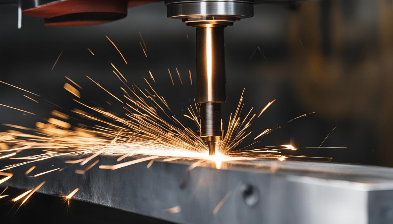
Achieving superior thread quality and preventing assembly issues in CNC machining often involves specialized thread forms like Higbee and blunt start threads. These thread types are engineered to eliminate the sharp, incomplete leading edge of a standard thread, enhancing safety, improving engagement, and significantly reducing the risk of cross-threading. Implementing these features requires precise programming and a deep understanding of CNC capabilities.
Higbee cuts, also known as blunt start or quick start threads, remove the first incomplete thread at the part’s entrance. This modification provides a smoother, safer thread start, particularly beneficial for components requiring rapid or blind assembly, such as fire hose couplings where the Higbee cut originated.
Programming the Higbee Cut: G-Code Macros and Strategies
Implementing a Higbee cut on a CNC lathe typically involves using a grooving or parting tool after the main threading cycle. The objective is to remove the partial thread profile that forms at the start of the thread, leaving a clean, full-profile thread form from the very first engagement.
A common approach involves calibrating the grooving tool to the same Z-zero position as the threading tool. The grooving insert should be as wide as or wider than the thread form’s base. The G-code for the grooving tool then mirrors the threading cycle, but with a shortened Z-depth to only deburr the initial thread length.
For example, when cutting 10 TPI threads for a 1-inch length, the first thread’s length to deburr is Z minus 0.100 inches. The grooving tool is programmed to this depth, making a few deburring passes. Adjusting the starting X-value and spindle RPM can control the ramp angle of the deburred thread.
Some advanced CNC controllers and CAM software, like Fusion 360 or GibbsCAM, offer built-in functionalities or simplified methods for programming Higbee cuts. These often involve duplicating the threading operation and adjusting ‘Backside containment’ or ‘Thread Start Offset’ parameters to a full pitch, effectively removing the initial thread.
Precision Lead Thread Milling and Clean Entry
| Material Type | Cutting Speed (SFM) | Feed per Tooth (IPT) | Coolant Recommendation |
|---|---|---|---|
| Aluminum Alloys | 300-500 | 0.001-0.003 | Flood coolant |
| Mild Steel | 250-350 | 0.001-0.003 | Flood coolant |
| Stainless Steel | 150-250 | 0.0008-0.002 | High-pressure coolant |
| Hardened Steel | 50-225 | 0.0002-0.0006 | High-pressure coolant |
| Titanium Alloys | 50-200 | 0.0003-0.0008 | High-pressure coolant |
Thread milling, a subtractive manufacturing technique, uses a specialized rotating tool following a helical path to create threads. This method offers superior control over thread diameter, pitch, and depth, making it ideal for precision applications and challenging materials like hardened steels or titanium.
Achieving precision in thread milling relies on accurate helical interpolation, where the X and Y axes move circularly while the Z-axis moves linearly to define the thread’s pitch. Smooth ‘arc-in’ and ‘arc-out’ movements are crucial for clean thread entry and exit, preventing chatter and extending tool life.
For internal threads, the minor diameter must be pre-drilled to the appropriate size. The thread mill then enters the hole, typically with a 180-degree lead-in helix, before milling the thread through helical motion. A corresponding 180-degree lead-out helix ensures a clean exit.
Multiple passes are often beneficial, especially for deep threads, coarse pitches, or hard materials. This strategy reduces tool deflection, improves chip evacuation, and enhances thread tolerance and surface finish.
Optimizing Feeds, Speeds, and Tolerances for Thread Milling
Proper feeds and speeds are paramount for successful thread milling, directly impacting thread quality, tool life, and machining time. These parameters must be carefully selected based on the workpiece material, cutter diameter, and thread specifications.
General guidelines suggest cutting speeds of 300-600 SFM for aluminum and 100-300 SFM for steel, with adjustments for specific alloys. Feed per tooth (chip load) typically ranges from 0.001-0.002 inches for small threads and up to 0.003-0.006 inches for larger threads.
Thread tolerances define the acceptable dimensional limits for threaded fasteners, ensuring proper fit and function. High-precision applications may demand tolerances as tight as ±0.0005 inches for pitch diameter, while general machining allows ±0.001 inches.
Tolerance grades, indicated by a number (e.g., 6 for standard, lower for tighter), and tolerance fields, denoted by a letter (e.g., H for internal, g for external), specify the precision and fit. Selecting the correct tolerance class balances performance requirements with manufacturing costs.
Preventing Cross-Threading and Ensuring Thread Integrity
Cross-threading occurs when male and female threads are misaligned, causing the threads to cut into each other instead of engaging properly. This can lead to stripped threads, seized components, and compromised joint integrity.
Beyond Higbee cuts, several CNC programming and operational practices prevent cross-threading. Ensuring precise alignment of the tool and workpiece is fundamental. For manual assembly, starting fasteners by hand and turning counter-clockwise until a ‘click’ indicates proper alignment is a common technique.
Maintaining machine rigidity is critical to prevent vibration and ensure accuracy during threading operations. Minimizing tool overhang, securing the workpiece with high-quality fixtures, and regularly checking machine condition for play in moving components are essential steps.
Regular maintenance, especially inspecting spindle encoder timing belts, is crucial for machines performing threading operations. Worn belts can cause positional feedback errors, leading to misalignment and cross-threading during re-pass operations.
Automated Thread Start Deburring Techniques
Burrs are an inevitable byproduct of threading processes and can form on almost any area of internal or external threads. Removing these burrs is critical for proper assembly, function, and overall part quality.
Automating thread deburring on CNC machines offers efficiency and reliability over manual methods. Specialized deburring brushes, such as Xebec Surface Brushes and Wheel Brushes, can be integrated into CNC programs to remove burrs from internal and external threads.
Programming deburring operations involves using a standard thread cycle with appropriate infeed data, ensuring the tool exits the thread at a 45-degree angle. The deburring length is typically programmed to one pitch before the 45-degree exit.
When using abrasive tools for deburring, careful consideration of feed and contact depth is necessary, as these strongly influence the edge break. Spindle speed changes cutting frequency and heat, requiring a balanced approach to achieve consistent results without damaging the thread profile.