
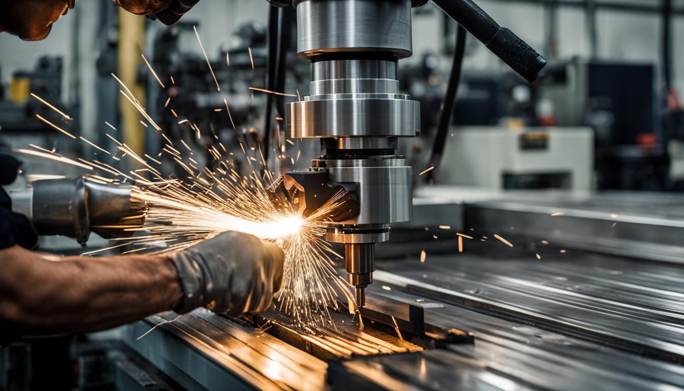
Integrating C-axis control and live tooling on CNC lathes transforms traditional turning centers into powerful multi-tasking machines. This advanced capability allows for the complete machining of complex parts in a single setup, significantly reducing production time and enhancing precision. Manufacturers can now perform milling, drilling, and tapping operations directly on the lathe, eliminating the need for multiple machine transfers.
This unified approach streamlines workflows, minimizes potential errors from re-chucking, and optimizes floor space. The ability to execute diverse operations on one machine is a cornerstone of modern manufacturing efficiency.
C-Axis Control and Spindle Indexing Precision
The C-axis in CNC lathes provides controlled rotational positioning of the workpiece around its center, typically aligned with the Z-axis. Unlike conventional lathes limited to X and Z linear movements, the C-axis enables precise angular orientation, crucial for machining features requiring exact alignment.
Spindle indexing, a core function of C-axis control, allows the main spindle to stop and hold the workpiece at specific angular positions. This capability is fundamental for performing off-center operations like drilling, milling, and tapping around the part’s circumference.
Modern C-axis systems operate through precise servo motor controls and programmable controllers, ensuring accurate positioning and movement. This integration expands machine capabilities significantly, allowing for complex shapes and features to be created with high precision and an improved surface finish.
Integrating Live Rotary End Mills
| Parameter | CNC Turning (Standard) | CNC Milling (Standard) | Live Tooling Milling on Lathe (General) |
|---|---|---|---|
| Typical Tolerance Capability | ±0.02 mm or better | ±0.025 mm | ISO 2768-m (e.g., ±0.20 mm for 3-30mm features) |
| High-Precision Tolerance | IT5-IT6 (e.g., 0.011-0.016 mm for 50mm nominal) | Up to ±0.01 mm | ±0.025–0.050 mm for critical features |
| Surface Finish (Ra) | 0.8–3.2 μm | Excellent for flat faces | Dependent on tool, material, and parameters |
| Feed Rate (Turning) | 0.005–0.020 in/rev (roughing), 0.002–0.004 in/rev (finishing) | N/A | N/A |
| Feed Rate (Milling) | N/A | Inches per minute (IPM) | Inches per minute (IPM) |
| Live Tool Spindle Speed (Max) | N/A | N/A | 3000-8000 RPM (depending on holder) |
Live tools are motorized tool holders integrated into the CNC lathe’s turret, rotating independently of the main spindle. These powered tools enable milling, drilling, and tapping directly on the lathe, eliminating the need to transfer workpieces to separate milling machines.
Common types of live tool holders include axial and radial ER collet holders, designed for various applications. Axial holders are suitable for drilling, reaming, and light milling along the workpiece axis, while radial (90°) holders excel at side milling, groove cutting, and cross-drilling.
Tool selection for live milling operations on a lathe requires considering the tool holder interface, with VDI and BMT being dominant systems. BMT (base-mount turret) holders offer a stiffer, more repeatable mount for heavier cuts, while VDI (Verein Deutscher Ingenieure) holders provide flexibility and faster changes.
Advanced Off-Center Drilling and Cross-Milling
Off-center drilling on a CNC lathe utilizes the C-axis to precisely position the workpiece at a specific angular offset, allowing a live drill bit to create holes not on the centerline. This technique is vital for components requiring eccentric features.
Cross-drilling involves drilling holes radially into the workpiece, perpendicular to the main spindle axis. With C-axis and live tooling, these operations are programmed by coordinating the C-axis with X and Z movements, and often a Y-axis for true off-center capabilities.
Milling flats on turned shafts is another common application, where the C-axis indexes the part, and a live end mill cuts the flat surface. For more complex contoured keyways or profiles, the C-axis can rotate synchronously with the live end mill’s X and Z movements.
Optimizing Multi-Tasking Lathe Setups
Multi-tasking lathes, also known as mill-turn machines, combine turning and milling capabilities into a single platform, offering significant advantages in precision and productivity. This integration reduces setup times, minimizes workpiece handling, and enhances overall accuracy by maintaining a single datum reference.
Workholding is critical for multi-tasking operations, demanding high repeatability and stability. Zero-point clamping systems and robust chucks are essential to ensure consistent part location and prevent movement during complex machining cycles.
Tool path generation for turn-mill operations requires advanced CAM software to design intricate multi-axis tool paths and simulate machining processes, preventing collisions and optimizing efficiency. Shorter tooling is often preferred in multi-tasking machines to improve maneuverability within the limited work envelope and enhance stability.
General guidelines for feeds and speeds in live tooling milling on lathes depend heavily on material, tool diameter, and machine rigidity. For instance, a 1/4-inch carbide end mill in 6061 aluminum might run around 700 SFM with a 0.0025-inch chip load, adjusting RPM based on spindle limits.
Standard tolerances for milled features on turned parts often reference ISO 2768-m for general dimensions, which sets ±0.20 mm for features between 3–30 mm and ±0.30 mm for 30–120 mm. For precision features like bearing bores, a working range of ±0.025–0.050 mm is common, with tighter tolerances requiring specialized processes.