
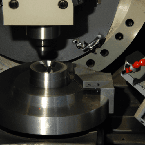
Turning is a fundamental subtractive manufacturing process that shapes a rotating workpiece using a stationary cutting tool. This versatile machining method is performed on a lathe, which can be manual or computer numerical control (CNC) driven, to create parts with rotational symmetry. Turning is essential across numerous industries, from aerospace to medical device manufacturing, due to its ability to achieve high precision and excellent surface finishes.
The core principle involves the workpiece spinning at high speeds while a single-point cutting tool engages its surface, progressively removing material. This action allows for the creation of various features, including external and internal cylindrical surfaces, conical shapes, grooves, and threads. Modern CNC lathes enhance this process by automating tool movements and ensuring exceptional accuracy and repeatability.
Making Cylindrical Shafts
Producing cylindrical shafts is a primary application of turning, involving the reduction of a workpiece’s diameter to a specified dimension. This process, often termed ‘straight turning’ or ‘step turning,’ is crucial for components like axles, pistons, and drive shafts that require precise rotational symmetry. Step turning specifically creates multiple diameters along a single shaft, forming distinct perpendicular transitions for mating components such as bearings or gears.
Achieving tight tolerances, typically within ±0.01mm for precision applications in materials like aluminum or steel, is paramount for shaft functionality. Concentricity and surface finish are critical considerations, especially for bearing seats or other high-wear areas. Roughing passes remove the bulk of material, while subsequent finishing passes refine the diameter and surface quality.
For turning steel shafts, recommended cutting speeds for carbide tooling can range from 200-250 SFM for 304 stainless steel, with feed rates between 0.002-0.006 inches per tooth (IPT) for a 1/2″ end mill. Aluminum alloys, such as 6061, typically allow for higher cutting speeds, often between 600 to 1200 SFM with carbide tooling, and feed rates from 0.004 to 0.010 IPR for roughing.
Cutting External Threads
| Operation / Material | Cutting Speed (SFM) | Feed Rate (IPR/IPT) | Typical Tolerance |
|---|---|---|---|
| Shaft Turning (Aluminum 6061, Carbide) | 600-1200 | 0.004-0.010 IPR (Roughing) | ±0.01mm |
| Shaft Turning (304 Stainless, Carbide) | 200-250 | 0.002-0.006 IPT (End Mill) | ±0.01mm |
| External Threading (Aluminum, Carbide) | ~490 (150 m/min) | Pitch-dependent | ISO/ANSI standards |
| External Threading (Steel, Carbide) | 80-120 | Pitch-dependent | ISO/ANSI standards |
| Boring (General, Carbide) | Material-dependent | 0.004-0.008 IPR (0.1-0.2 mm/rev) | ±0.01mm |
| Facing (304/316 Stainless, Indexable) | 600-800 | 0.0015-0.002 IPT | ~0.001-0.003″ surface finish |
External thread cutting on a lathe involves precisely forming helical grooves on the outer surface of a cylindrical workpiece. This operation is vital for creating fasteners, adjusting mechanisms, and connecting components. Both single-point threading tools and threading dies can be employed, with single-point turning offering greater flexibility for various thread forms and pitches.
The process requires careful synchronization of the cutting tool’s axial movement with the workpiece’s rotation, typically controlled by the lathe’s lead screw. For CNC machines, G-code programming dictates the exact pitch and depth of cut. Standard thread tolerances are critical for proper fit and function, often adhering to ISO or ANSI standards.
When cutting threads, material selection significantly impacts speeds and feeds. For aluminum, cutting speeds can be as high as 150 m/min (approximately 490 SFM), while steel typically requires moderate speeds of 80-120 SFM. Stainless steel and titanium demand even slower speeds to prevent work hardening and excessive tool wear.
Boring Inner Diameters
Boring is a precision machining operation used to enlarge and true existing holes, ensuring tight size, straightness, concentricity, and surface finish. This process is typically performed after drilling, especially when the initial drilled hole cannot meet the required final tolerance or positional accuracy. Boring utilizes a single-point cutting tool mounted on a rigid boring bar.
The tool cuts on one side of the hole, allowing the machine to precisely offset the centerline to its true position, making it more accurate than reaming for correcting mislocated or out-of-round holes. CNC boring can achieve tolerances around ±0.01 mm, with finer results possible through optimized tooling and thermal control.
Typical starting feed rates for boring operations range from 0.1 to 0.2 mm per revolution, with cutting speeds varying based on material and tool type. For aluminum, higher speeds are generally used, while harder materials like steel require reduced speeds to maintain tool life and bore quality. Proper coolant application is essential to manage heat and facilitate chip evacuation.
Creating Pulleys and Pins
Turning is indispensable for manufacturing components like pulleys and pins, which demand precise cylindrical forms and specific features. Pulleys, for instance, require accurate outer diameters, bored center holes for shafts, and precisely cut belt grooves to ensure efficient power transmission. Pins often need tight diameter tolerances for press-fit or clearance applications.
Machinists typically start with solid round stock, turning it to the target outer diameter before boring the center hole and profiling any grooves. For metal pulleys, aluminum or steel are common choices. Aluminum cuts easily but requires sharp tools and moderate speeds to prevent material tearing.
When creating pulleys, the internal diameter must be accurate for a proper fit with the shaft, often requiring a tight friction fit or a keyway for torque transmission. Tolerances for bores and keyways are critical, influencing the assembly’s functionality and longevity.
Facing Round Bar Stock
Facing is a fundamental turning operation that creates a flat, perpendicular surface on the end of a workpiece, effectively reducing its length. This process establishes a critical datum surface, ensuring subsequent cuts align correctly and parts meet specified lengths. It is often one of the first operations performed on raw bar stock.
The cutting tool, typically a straight cutting or facing tool, is positioned at the workpiece’s center height and fed radially inward across the end face. Roughing passes remove significant material, while a final finishing pass, often with a shallower depth of cut (0.001 to 0.003 inches) and higher RPM, achieves a smooth surface finish.
For facing stainless steel, typical parameters for a 2.5-inch indexable face mill include 600–800 RPM and 10–12 IPM feed, aiming for a chip load of 0.0015–0.002 inches per insert. Achieving a mirror-like finish on 303 stainless steel can involve converting a multi-insert face mill into a flycutter, using a single insert at 800–1200 RPM, 12–18 IPM feed, and a shallow depth of cut (0.015–0.025 inches).